
Uncategorized
Getting Started with Aptinex CAN – ISO Module
Aug
What is CAN protocol?
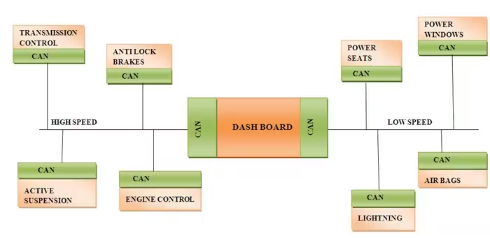
CAN stands for Controller Area Network which was first introduced as a data transmission protocol for automobiles. Modern automobiles have multiple electronic control and sensing systems in every component. Such as the Engine Control Unit (ECU), Transmission Control system, ABS braking system, airbags, Power windows, Air conditioning, and dashboard. So communication method between those systems happens through CAN protocol. Due to higher reliability and cost-effectiveness, CAN is used in a wider range of industries other than automobiles such as industrial automation, aerospace, and medical devices.
Now it is time to dive down into the technical aspects of the CAN.
How CAN Works
CAN protocol is a serial two-wire differential data transmission technology. This uses two wires CANH(CAN High) and CANL(CAN Low).
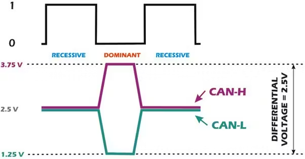
Take a look at the snapshot of CAN transmission above. As you can see Higher voltage differences between voltages are taken as logic 0 and lower voltage differences are taken as logic 1. This is how differential data transmission works.
Since the CAN working principle is differential signaling, It boasts longer transmission distances and higher noise immunity thus finding its use in Automotive and Industrial applications.
There are 2 CAN communication standards.
- CAN 2.0 – 8 bytes message length and up to 1Mbps data rate.
- CAN FD – FD stands for flexible data rate. Unlike the fixed data rate of CAN 2.0 data rates can be changed. Frame can hold 64 bytes and the maximum speed is 5Mbps which is an improvement over CAN 2.0.
The module supports both of the protocols.
CAN wiring
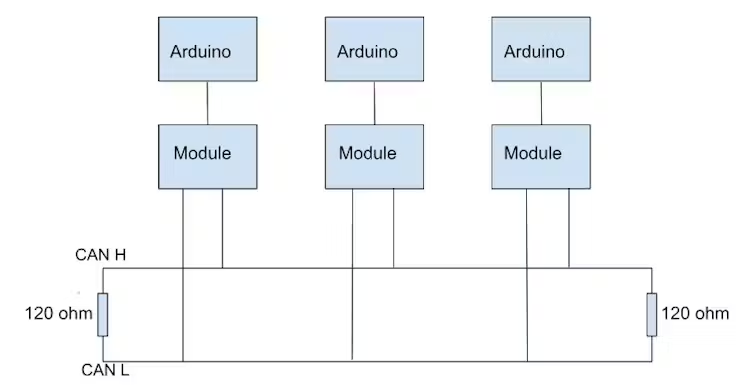
As you can see in the diagram above there are two 120 Ohm resistors at each end. This is to prevent the signal from bouncing back at the ends. CAN protocol support multiple devices at the same data lines.
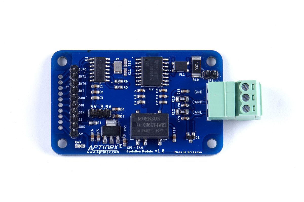
Aptinex Isolated SPI-CAN Module Features
- Maximum Transmission Rate – 5Mbps
- Supported CAN Protocols – CAN 2.0B and CAN FD
- Fully Isolation between the microcontroller interface and CAN connection.
- Jumper for switching between 3.3V and 5V logic levels.
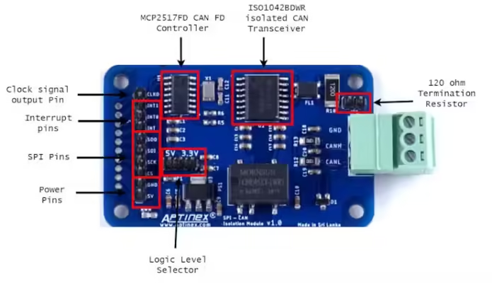
Now let’s take a look at each component of the module and their technical specifications.
MCP2517FD CAN FD Controller
The MCP2517FD is a cost-effective and small-footprint CAN FD Controller that can be easily added to a microcontroller with an available SPI interface. Therefore, a CAN FD channel can be easily added to a microcontroller that either lacks a CAN FD peripheral or doesn’t have enough CAN FD channels.
The MCP2517FD supports both, CAN frames in the Classical format (CAN2.0B) and CAN Flexible Data Rate (CAN FD) format, as specified in ISO 11898-1:2015.
Ideal passive, high-impedance bus terminals when unpowered
Arbitration Bit Rate up to 1 Mbps
Data Bit Rate up to 8 Mbps
31 FIFOs configurable as transmit or receive
32 Flexible Filter and Mask Objects
ISO1042BDWR CAN Transceiver
The ISO1042 device is a galvanically isolated controller area network (CAN) transceiver that meets the specifications of the ISO11898-2 (2016) standard. TheISO1042 device offers ±70-V DC bus fault protection and ±30-Common-mode voltage range.
Meets the ISO 11898-2:2016 physical layer standard
Supports classic CAN up to 1 Mbps and FD (Flexible Data Rate) up to 5 Mbps
Low loop delay: 152 ns
Protection features
DC bus fault protection voltage: ±70 V
HBM ESD tolerance on bus pins: ±16kV
Driver Dominant Time Out (TXD DTO)
Driver Dominant Time Out (TXD DTO)
Common-Mode Voltage Range: ±30 V
Ideal passive, high-impedance bus terminals when unpowered.
Now that you have got the basics of CAN and an overview of the module lets take a look at the examples.
Example 1 – Send and Receive data via CAN
First, connect the modules as mentioned below. Wiring connections are the same for both arduinos for simplicity.
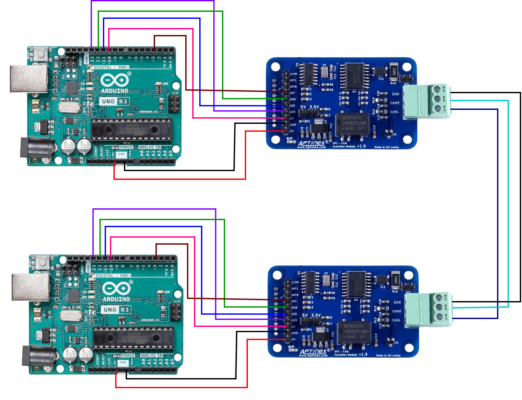
Now before we can upload the code to the Arduino it is necessary to set module jumpers correctly. Since we are using Arduino UNO with 5V logic set the logic level selector jumper to 5V. If you are using a 3.3V development board such as Raspberry Pi Pico you should set the jumper to 3.3V.
Earlier I explained about 120 Ohm termination resistor. Since each module is at the end of the 2-wire bus, the termination resistor needs to be connected across the two lines near each module. You do not need to add that resistor separately. This module has that resistor in-built. To add the resistor just connect the JP1 jumper.
CAN wire can be of any length. CAN can transmit around 30m effectively.
So that’s it for hardware setup. Now let’s move into the programming part.
To get started you need to download and install this library to Arduino IDE.
Here is the link-.Library GitHub Page
Click Code >> Download ZIP
Then in the Arduino IDE Click Sketch >> Include Library >> Add.ZIP Library then select the downloaded zip file to install library.
Transmitter
#include <SPI.h>
#include "mcp2518fd_can.h"
// pins for CAN-FD Shield
//const int SPI_CS_PIN = 9;
//const int CAN_INT_PIN = 2;
// pins for CANBed FD
const int SPI_CS_PIN = 10;
const int CAN_INT_PIN = 3;
mcp2518fd CAN(SPI_CS_PIN); // Set CS pin
void setup() {
Serial.begin(115200);
while(!Serial);
while (CAN_OK != CAN.begin(CAN20_500KBPS)) {             // init can bus : baudrate = 500k
Serial.println("CAN init fail, retry...");
delay(100);
}
Serial.println("CAN init ok!");
delay(1000);
}
unsigned char stmp[8] = {0, 1, 2, 3, 4, 5, 6, 7};
void loop() {
CAN.sendMsgBuf(0x01, 0, 8, stmp);       // send a standard frame to id 0x01
delay(10);
CAN.sendMsgBuf(0x04, 1, 8, stmp);       // send a extended frame to id 0x04
delay(100);                       // send data per 100ms
Serial.println("CAN BUS sendMsgBuf ok!");
delay(1000);
}
const int SPI_CS_PIN = 10 – Defines the SPI chip select pin connected to the MCP2518FD
const int CAN_INT_PIN = 3 – Defines the interrupt pin of the MCP2518FD
unsigned char stmp[8] = {0, 1, 2, 3, 4, 5, 6, 7} – Declares an array of size 8 containing data bytes to be transmitted in the CAN message. This is where you should put the preferred message to be sent.
CAN.sendMsgBuf(0x01, 0, 8, stmp) – Transmits a standard CAN message. Here’s what each parameter signifies:
- 0x01: This is the CAN identifier (ID) of the message, set to 1 in hexadecimal format.This ID is usefull when there is multiple devices transmitting on the same can bus. This allows the receiver to filter out unwanted messages. Furthermore, when two devices try to transmit CAN frames at the same time, the priority is given to the message with a lower ID.
- 0: This indicates a standard frame (11-bit ID) since the second parameter is 0. For extended frames (29-bit ID), a non-zero value would be used here.
- 8: This specifies the data length to be transmitted, which is 8 bytes in this case.
- stmp: This is the reference to the data array in which your preferred message is stored.
Receiver
#include <SPI.h>
#include "mcp2518fd_can.h"
// pinS for CAN-FD Shield,
//const int SPI_CS_PIN = 9;
//const int CAN_INT_PIN = 2;
// pinS for CANBed FD
const int SPI_CS_PIN = 10;
const int CAN_INT_PIN = 3;
mcp2518fd CAN(SPI_CS_PIN); // Set CS pin
void setup() {
Serial.begin(115200);
while(!Serial);
while (CAN_OK != CAN.begin(CAN20_500KBPS)) {             // init can bus : baudrate = 500k
Serial.println("CAN init fail, retry...");
delay(100);
}
Serial.println("CAN init ok!");
}
void loop() {
unsigned char len = 0;
unsigned char buf[8];
if (CAN_MSGAVAIL == CAN.checkReceive())         // heck if data coming
{
CAN.readMsgBuf(&len, buf);                  // You should call readMsgBuff before getCanId
unsigned long id = CAN.getCanId();
unsigned char ext = CAN.isExtendedFrame();
Serial.print(ext ? "GET EXTENDED FRAME FROM ID: 0X" : "GET STANDARD FRAME FROM ID: 0X");
Serial.println(id, HEX);
Serial.print("Len = ");
Serial.println(len);
// print the data
for (int i = 0; i < len; i++) {
Serial.print(buf[i]);
Serial.print("t");
}
Serial.println();
}
}
CAN.checkReceive() – This function checks if a CAN message is available for receiving continuously.
CAN.readMsgBuf(&len, buf) – Reads the received CAN message data into the “buf” array
unsigned long id = CAN.getCanId() – Reads the CAN identifier (ID) of the received message.
If the CAN transmission is successful, serial monitor output from the receiving end should look like this.
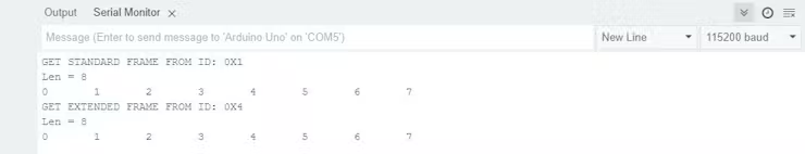
This way you can communicate back and forth using CAN.