
Uncategorized
Getting Started with Aptinex IsolPoE – ESP32 ProDev Kit
Aug
What is PoE
PoE stands for power over Ethernet, which means that both power and data can be transmitted through Ethernet cable, eliminating the need for separate power cables for devices with Ethernet connectivity.
They are widely used in powering VoIP Phones, Wireless APs, Security Cameras, and IoT Devices. This technology is used to an extent where that is even used to power LED lighting systems. So PoE is the future.
To get started with PoE just plug the Ethernet cable into the RJ45 port of the PoE supported device. PoE takes care of the power to the device.
In the EEE802.3af PoE standard each device can receive up to power of 30W. PoE normally transmits power at 48V AC.
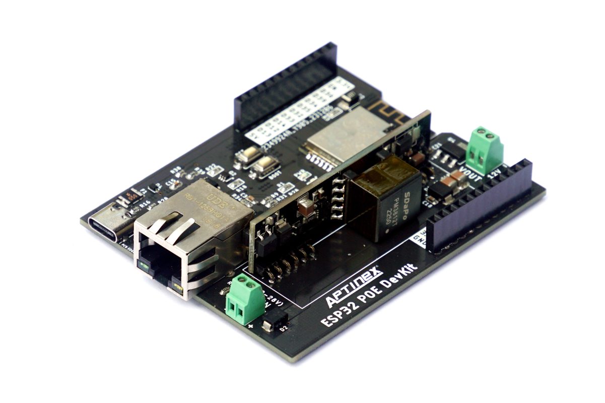
The ESP32 PoE DevKit
Let’s take a glance at the development board features
- ESP32
At the heart of our development board microcontroller module is the ESP-32s module. You can make use of existing programs and libraries written for ESP-32.
- LAN8720 Ethernet Controller
100BaseT Ethernet protocol transceiver to interface ESP32 with Ethernet. This can deliver data rates up to 100Mbps which is more than enough for microcontroller-based IoT applications.
- Isolated PoE
The SDAPO DP9700-12V module enables PoE functionality of the development board thus powering the board and isolation for extra safety. It has Short circuit protection and Over-current protection. This board has a screw terminal supplying 12V output from the PoE to power up extra modules and devices. It can deliver power up to 12W which would be more than enough to power up most power-hungry modules out there.
- USB-C
Supports modern, high-speed USB connectivity for efficient data transfer and device programming, aligning with current technological standards.
- Multiple GPIO Outputs
This development board has a total of 15 GPIO pins as well as 5V and 3.3V outputs.
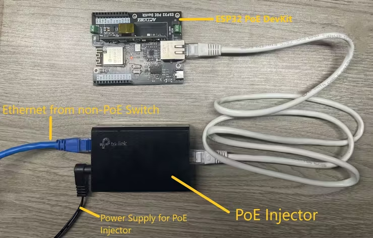
How to make use of PoE functionality.
1) If you have a PoE-supported switch setting up is straightforward. Just connect the Ethernet cable to the development board.
2) If you don’t have a PoE-supported switch, you should use a PoE injector. PoE injector adds electrical power to an Ethernet cable, allowing it to supply power to devices that support PoE.
Here I have used tp-link TL-POE150S PoE Injector.
Example 1 – Sending/Receiving UDP Packets
In this example, we are going to send UDP packets and listen for UDP packets. In this sketch, 2 libraries are used. You can download those libraries in the following links.
https://github.com/khoih-prog/WebServer_WT32_ETH01
https://github.com/khoih-prog/AsyncUDP_WT32_ETH01
#include <Arduino.h>
#define ASYNC_UDP_WT32_ETH01_DEBUG_PORT      Serial
// Use from 0 to 4. Higher number, more debugging messages and memory usage.
#define _ASYNC_UDP_WT32_ETH01_LOGLEVEL_ 1
#include <AsyncUDP_WT32_ETH01.h>
/////////////////////////////////////////////
// Select the IP address according to your local network
IPAddress myIP(192, 168, 1, 155);
IPAddress myGW(192, 168, 1, 1);
IPAddress mySN(255, 255, 255, 0);
// Google DNS Server IP
IPAddress myDNS(8, 8, 8, 8);
/////////////////////////////////////////////
#define ETH_CLK_MODE     ETH_CLOCK_GPIO0_IN
// Pin# of the enable signal for the external crystal oscillator (-1 to disable for internal APLL source)
#define ETH_PHY_POWER 17
// Type of the Ethernet PHY (LAN8720 or TLK110)
#define ETH_PHY_TYPE        ETH_PHY_LAN8720
// I²C-address of Ethernet PHY (0 or 1 for LAN8720, 31 for TLK110)
#define ETH_PHY_ADDR 1
// Pin# of the I²C clock signal for the Ethernet PHY
#define ETH_PHY_MDC 23
// Pin# of the I²C IO signal for the Ethernet PHY
#define ETH_PHY_MDIO 18
//UDP Port number
#define udp_port 1234
AsyncUDP udp;
void setup()
{
Serial.begin(115200);
while (!Serial);
Serial.print("nStarting Async_UDPClient on " + String(ARDUINO_BOARD));
Serial.println(" with " + String(SHIELD_TYPE));
Serial.println(WEBSERVER_WT32_ETH01_VERSION);
Serial.println(ASYNC_UDP_WT32_ETH01_VERSION);
Serial.setDebugOutput(true);
delay(3000);
// To be called before ETH.begin()
WT32_ETH01_onEvent();
//bool begin(uint8_t phy_addr=ETH_PHY_ADDR, int power=ETH_PHY_POWER, int mdc=ETH_PHY_MDC, int mdio=ETH_PHY_MDIO,
//           eth_phy_type_t type=ETH_PHY_TYPE, eth_clock_mode_t clk_mode=ETH_CLK_MODE);
//ETH.begin(ETH_PHY_ADDR, ETH_PHY_POWER, ETH_PHY_MDC, ETH_PHY_MDIO, ETH_PHY_TYPE, ETH_CLK_MODE);
ETH.begin(ETH_PHY_ADDR, ETH_PHY_POWER, ETH_PHY_MDC, ETH_PHY_MDIO, ETH_PHY_TYPE, ETH_CLK_MODE);
// Static IP, leave without this line to get IP via DHCP
//bool config(IPAddress local_ip, IPAddress gateway, IPAddress subnet, IPAddress dns1 = 0, IPAddress dns2 = 0);
ETH.config(myIP, myGW, mySN, myDNS);
WT32_ETH01_waitForConnect();
// Client address
Serial.print("AsyncUDPServer started @ IP address: ");
Serial.println(ETH.localIP());
if (udp.listen(udp_port))
{
Serial.print("UDP Listening on IP: ");
Serial.println(ETH.localIP());
udp.onPacket([](AsyncUDPPacket packet)
{
Serial.print("UDP Packet Type: ");
Serial.print(packet.isBroadcast() ? "Broadcast" : packet.isMulticast() ? "Multicast" : "Unicast");
Serial.print(", From: ");
Serial.print(packet.remoteIP());
Serial.print(":");
Serial.print(packet.remotePort());
Serial.print(", To: ");
Serial.print(packet.localIP());
Serial.print(":");
Serial.print(packet.localPort());
Serial.print(", Length: ");
Serial.print(packet.length());
Serial.print(", Data: ");
Serial.write(packet.data(), packet.length());
Serial.println();
//reply to the client
packet.printf("Got %u bytes of data", packet.length());
});
}
The below line can be used to change the port for the UDP.
//UDP Port number
#define udp_port 1234//UDP Port number
This line sets the IP address of the Ethernet interface of the board.
IPAddress myIP(192, 168, 1, 155);
The current IP is I92.168.1.155
By changing the text in the following line you can change the UDP message being broadcasted.
udp.broadcast("Hello");
To upload the sketch to the board you should select “Node32s” in the board selection and set the proper COM port.

To receive the UDP packets sent by the board and send back UDP packets to the board from the computer I used SocketTest.

To listen to the UDP packets sent over ethernet set the port to “1234” and click “Start Listening”.As you can see above the message “Hello” should be displayed in the window.
To send a UDP packet destined for the DevKit Set the board ethernet IP address in the client section below. In this case, the IP is 192.168.1.155. Then set port to 1234. Type the message and click “Send”.
The received message should be displayed in the Serial monitor.

Serial monitor output when It has received the UDP message.
Example 2 – Controlling Relays from Smartphone
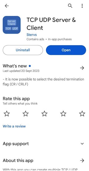
In this example, we are going to control relays over ethernet using UDP. Unlike the previous example, we are using a smartphone to send UDP commands to the board. To send or receive UDP packets you may use any suitable app for this purpose. There are many apps available in the Google Play Store or Apple App Store.
Here I have used the “TCP UDP Server & Client ” app from the Google PlayStore.
Here is the code.
#include <Arduino.h>
#define ASYNC_UDP_WT32_ETH01_DEBUG_PORT Serial
// Use from 0 to 4. Higher number, more debugging messages and memory usage.
#define _ASYNC_UDP_WT32_ETH01_LOGLEVEL_ 1
#include <AsyncUDP_WT32_ETH01.h>
/////////////////////////////////////////////
// Select the IP address according to your local network
IPAddress myIP(192, 168, 1, 155);
IPAddress myGW(192, 168, 1, 1);
IPAddress mySN(255, 255, 255, 0);
// Google DNS Server IP
IPAddress myDNS(8, 8, 8, 8);
/////////////////////////////////////////////
#define ETH_CLK_MODE ETH_CLOCK_GPIO0_IN
// Pin# of the enable signal for the external crystal oscillator (-1 to disable for internal APLL source)
#define ETH_PHY_POWER 17
// Type of the Ethernet PHY (LAN8720 or TLK110)
#define ETH_PHY_TYPE ETH_PHY_LAN8720
// I²C-address of Ethernet PHY (0 or 1 for LAN8720, 31 for TLK110)
#define ETH_PHY_ADDR 1
// Pin# of the I²C clock signal for the Ethernet PHY
#define ETH_PHY_MDC 23
// Pin# of the I²C IO signal for the Ethernet PHY
#define ETH_PHY_MDIO 18
// UDP Port number
#define udp_port 1234
// Onboard LED pin
#define ONBOARD_LED_PIN 2  // Replace with the correct pin for your board
//Define Relay Pins
#define Relay1_pin 12
#define Relay2_pin 14
AsyncUDP udp;
void setup() {
Serial.begin(115200);
while (!Serial)
;
Serial.print("nStarting Async_UDPClient on " + String(ARDUINO_BOARD));
Serial.println(" with " + String(SHIELD_TYPE));
Serial.println(WEBSERVER_WT32_ETH01_VERSION);
Serial.println(ASYNC_UDP_WT32_ETH01_VERSION);
Serial.setDebugOutput(true);
delay(3000);
// To be called before ETH.begin()
WT32_ETH01_onEvent();
// ETH.begin(ETH_PHY_ADDR, ETH_PHY_POWER, ETH_PHY_MDC, ETH_PHY_MDIO, ETH_PHY_TYPE, ETH_CLK_MODE);
ETH.begin(ETH_PHY_ADDR, ETH_PHY_POWER, ETH_PHY_MDC, ETH_PHY_MDIO, ETH_PHY_TYPE, ETH_CLK_MODE);
// Static IP, leave without this line to get IP via DHCP
ETH.config(myIP, myGW, mySN, myDNS);
WT32_ETH01_waitForConnect();
// Client address
Serial.print("AsyncUDPServer started @ IP address: ");
Serial.println(ETH.localIP());
if (udp.listen(udp_port)) {
Serial.print("UDP Listening on IP: ");
Serial.println(ETH.localIP());
udp.onPacket([](AsyncUDPPacket packet) {
Serial.print("UDP Packet Type: ");
Serial.print(packet.isBroadcast() ? "Broadcast" : packet.isMulticast() ? "Multicast"
: "Unicast");
Serial.print(", From: ");
Serial.print(packet.remoteIP());
Serial.print(":");
Serial.print(packet.remotePort());
Serial.print(", To: ");
Serial.print(packet.localIP());
Serial.print(":");
Serial.print(packet.localPort());
Serial.print(", Length: ");
Serial.print(packet.length());
Serial.print(", Data: ");
Serial.write(packet.data(), packet.length());#include <Arduino.h>
#define ASYNC_UDP_WT32_ETH01_DEBUG_PORT Serial
// Use from 0 to 4. Higher number, more debugging messages and memory usage.
#define _ASYNC_UDP_WT32_ETH01_LOGLEVEL_ 1
#include <AsyncUDP_WT32_ETH01.h>
/////////////////////////////////////////////
// Select the IP address according to your local network
IPAddress myIP(192, 168, 1, 155);
IPAddress myGW(192, 168, 1, 1);
IPAddress mySN(255, 255, 255, 0);
// Google DNS Server IP
IPAddress myDNS(8, 8, 8, 8);
/////////////////////////////////////////////
#define ETH_CLK_MODE ETH_CLOCK_GPIO0_IN
// Pin# of the enable signal for the external crystal oscillator (-1 to disable for internal APLL source)
#define ETH_PHY_POWER 17
// Type of the Ethernet PHY (LAN8720 or TLK110)
#define ETH_PHY_TYPE ETH_PHY_LAN8720
// I²C-address of Ethernet PHY (0 or 1 for LAN8720, 31 for TLK110)
#define ETH_PHY_ADDR 1
// Pin# of the I²C clock signal for the Ethernet PHY
#define ETH_PHY_MDC 23
// Pin# of the I²C IO signal for the Ethernet PHY
#define ETH_PHY_MDIO 18
// UDP Port number
#define udp_port 1234
// Onboard LED pin
#define ONBOARD_LED_PIN 2  // Replace with the correct pin for your board
//Define Relay Pins
#define Relay1_pin 12
#define Relay2_pin 14
AsyncUDP udp;
void setup() {
Serial.begin(115200);
while (!Serial)
;
Serial.print("nStarting Async_UDPClient on " + String(ARDUINO_BOARD));
Serial.println(" with " + String(SHIELD_TYPE));
Serial.println(WEBSERVER_WT32_ETH01_VERSION);
Serial.println(ASYNC_UDP_WT32_ETH01_VERSION);
Serial.setDebugOutput(true);
delay(3000);
// To be called before ETH.begin()
WT32_ETH01_onEvent();
// ETH.begin(ETH_PHY_ADDR, ETH_PHY_POWER, ETH_PHY_MDC, ETH_PHY_MDIO, ETH_PHY_TYPE, ETH_CLK_MODE);
ETH.begin(ETH_PHY_ADDR, ETH_PHY_POWER, ETH_PHY_MDC, ETH_PHY_MDIO, ETH_PHY_TYPE, ETH_CLK_MODE);
// Static IP, leave without this line to get IP via DHCP
ETH.config(myIP, myGW, mySN, myDNS);
WT32_ETH01_waitForConnect();
// Client address
Serial.print("AsyncUDPServer started @ IP address: ");
Serial.println(ETH.localIP());
if (udp.listen(udp_port)) {
Serial.print("UDP Listening on IP: ");
Serial.println(ETH.localIP());
udp.onPacket([](AsyncUDPPacket packet) {
Serial.print("UDP Packet Type: ");
Serial.print(packet.isBroadcast() ? "Broadcast" : packet.isMulticast() ? "Multicast"
: "Unicast");
Serial.print(", From: ");
Serial.print(packet.remoteIP());
Serial.print(":");
Serial.print(packet.remotePort());
Serial.print(", To: ");
Serial.print(packet.localIP());
Serial.print(":");
Serial.print(packet.localPort());
Serial.print(", Length: ");
Serial.print(packet.length());
Serial.print(", Data: ");
In this Arduino sketch, the loop section is blank. But how does the program look for UDP packets and turn on/off the relays? Listening for UDP packets happens in the background. That’s how the AsyncUDP_WT32_ETH01 Library is supposed to work.
The code section where the program analyzes the UDP packets and changes the states of the relays accordingly is shown below. Relay pins are D12 and D14.
// Check the received message
String receivedMsg = String((char *)packet.data());
// Check if the message is "R1_ON", turn on the Relay 1
if (receivedMsg == "R1_ON") {
digitalWrite(Relay1_pin, HIGH);
udp.broadcast("Relay 1 turned on");
Serial.println("Relay 1 turned on");
}
// Check if the message is "R1_OFF", turn off the Relay 1
else if (receivedMsg == "R1_OFF") {
digitalWrite(Relay1_pin, LOW);
udp.broadcast("Relay 1 turned off");
Serial.println("Relay 1 turned off");
}
//Check if the message is "R2_ON", turn on the Relay 2
else if (receivedMsg == "R2_ON") {
digitalWrite(Relay2_pin, HIGH);
udp.broadcast("Relay 2 turned on");
Serial.println("Relay 2 turned on");
}
// Check if the message is "R2_OFF", turn off the Relay 2
else if (receivedMsg == "R2_OFF") {
digitalWrite(Relay2_pin, LOW);
udp.broadcast("Relay 2 turned off");
Serial.println("Relay 2 turned off");
}
Connect the D12 and D14 pins to Input 1 and Input 2 of the relay board. Then power the 12V relay module from the 12V OUT screw terminal.
After uploading the sketch to the board I created a UDP server from the mobile App specifying the correct port 1234.
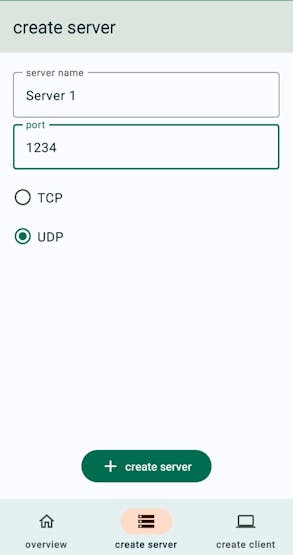
Now To control the relay from the smartphone all you need to do is send UDP messages below
“R1_ON” – To turn on the relay 1
“R1_OFF” – To turn off the relay 1
“R2_ON” – To turn on the relay 2
“R2_OFF” – To turn off the relay 2
Make sure your smartphone is connected to same LAN as the development board.
As you can see the 12V relay module is directly powered from the 12V output from the board. The power is directly drawn from the PoE. The power that can be delivered is 12W and the current is around 1A.