
Uncategorized
Getting Started with DAGAYA Surge Duo Motor Driver
Aug
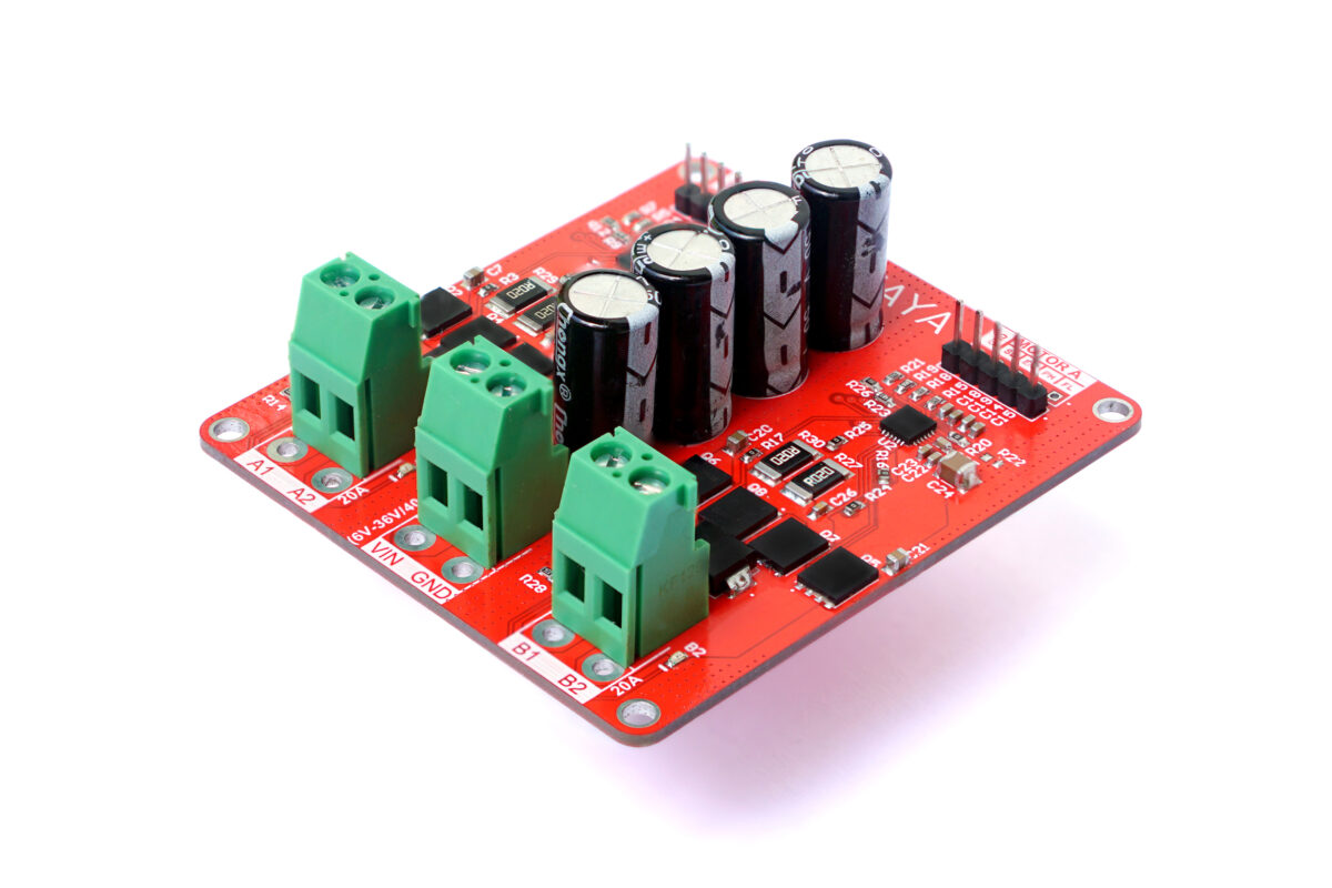
The “DAGAYA” is a powerful and adaptable dual motor driver designed to drive two high-current brushed DC motors concurrently. Utilizing the DRV8701 gate drivers, this motor driver ensures exceptional performance, efficiency, and reliability. Designed for versatility, it provides precise control and robust protection, making it ideal for a wide range of challenging applications that demand consistent and efficient motor operation.
Features
Dual H-Bridge Configuration:
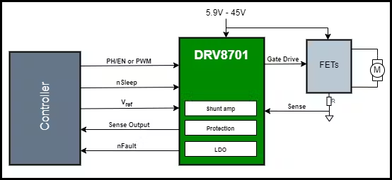
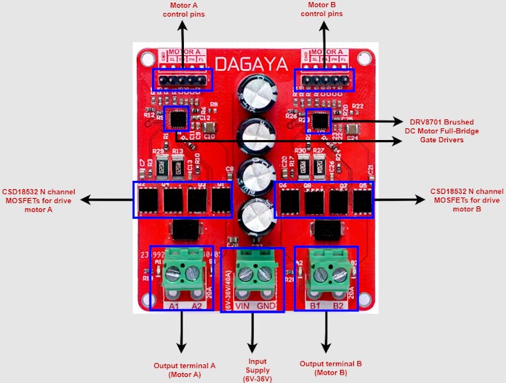
The DAGAYA Surge Duo features two independent H-Bridge circuits powered by DRV8701ERGER gate drivers, enabling precise, bidirectional control of two high-power brushed DC motors. This setup is perfect for applications that demand smooth acceleration, controlled deceleration, and precise torque management and supports 100% of PWM duty cycle.
Wide Voltage Range:
Operating across a broad voltage range of 6V to 36V, the DAGAYA Surge Duo is highly versatile, making it suitable for a wide array of power sources. Whether in industrial environments or mobile robotic platforms, this driver delivers the flexibility required to meet diverse power needs.
High-Current MOSFETs:
Equipped with CSD18532Q5BT MOSFETs, the DAGAYA Surge Duo can handle significant current loads while minimizing heat buildup. The efficient H-Bridge design reduces power loss, ensuring optimal performance even under heavy operational demands.
Adjustable Gate Drive Current:
Customize the gate drive current between 6mA and 150mA source current and 12.5-mA to 300-mA sink Current to match your specific MOSFETs and application requirements. This adjustable feature optimizes performance, reduces unnecessary heat, and extends the lifespan of the driver components.
Advanced Protection Mechanisms:
The DAGAYA Surge Duo integrates several protection features to ensure reliable operation:
- Overcurrent Protection: Limits current to prevent potential damage to the system.
- Thermal Shutdown: Automatically disables the driver if temperatures exceed safe thresholds.
- Undervoltage Lockout (UVLO): Safeguards the driver and motors from unstable power conditions.
- Fault Reporting: Built-in diagnostics provide instant feedback on any issues, facilitating quick troubleshooting.
Low Power Sleep Mode:
The DAGAYA Surge Duo includes a low-power sleep mode that reduces power consumption when the driver is inactive. This feature is especially valuable in battery-powered applications, helping to extend overall operational time.
Precision Control Interface:
Supporting both PH/EN and PWM control interfaces, the DAGAYA Surge Duo offers precise speed and direction control. Its compatibility with a wide range of microcontrollers and control systems makes it a versatile choice for various applications.
Compact and Efficient Design:
The PCB layout is meticulously optimized for low resistance and effective heat dissipation. The compact form factor ensures easy integration into existing systems without compromising on performance, making the DAGAYA Surge Duo a highly efficient and space-saving solution.
Logic Input Compatibility:
The DAGAYA Surge Duo is designed to support logic inputs of 1.8V, 3.3V, and 5V, ensuring broad compatibility with a wide range of microcontrollers and control systems.
Max Current: 40A (20APer Motor)
The DAGAYA Surge Duo motor driver is capable of handling a maximum current of 20A per motor, making it suitable for high-power applications. This high current capacity ensures that the driver can operate powerful motors, providing the necessary torque and speed.
Applications of DAGAYA Surge Duo
- Industrial Automation
- Robotics
- Home Automation
Pin Configuration
EN – Bridge Enable input. When the EN pin is in logic low motor enters the brake mode.
PH – Bridge phase input. This pin controls the direction of the motor.
SL – Device sleep mode. When this pin is in logic low device is in low power sleep mode.
GND– Connects to Ground.
When,
SL=0 ; EN=X ; PH=X ; >>>>>>>Sleep Mode
SL=1 ; EN=0 ; PH=X ; >>>>>>>Brake
SL=1 ; EN=1 ; PH=0 ; >>>>>>>Reverse Drive
SL=1 ; EN=1 ; PH=1 ; >>>>>>>Forward Drive
Testing DAGAYA Surge Duo
- Connect DAGAYA Surge Duo Motor Driver with Microcontroller as follows.

- Upload the below code to the Arduino.
const int motorPin = 9; // Pin connected to motor driver input
const int phasePin = 10; //pin connected to PH pin

void setup() {
  pinMode(motorPin, OUTPUT); // Set motorPin as an output
}

void loop() {

digitalWrite(phasePin, HIGH); // sets the direction to forward
delay(5000);

  digitalWrite(motorPin, HIGH);//motor runs in full speed for 3 sec
  delay(3000);
  digitalWrite(motorPin, LOW);//motor breaks for 1 sec
  delay(1000);

  // Change the motor speed gradually from 0 to 255 and back to 0
  for (int speed = 0; speed <= 255; speed++) {
    analogWrite(motorPin, speed); // Set motor speed
    delay(300); // Adjust delay for speed change
  }
  for (int speed = 255; speed >= 0; speed--) {
    analogWrite(motorPin, speed); // Set motor speed
    delay(300); // Adjust delay for speed change
  }

digitalWrite(phasePin, LOW);  // Change the direction to backward
delay(1000);

// Change the motor speed gradually from 0 to 255 and back to 0
  for (int speed = 0; speed <= 255; speed++) {
    analogWrite(motorPin, speed); // Set motor speed
    delay(300); // Adjust delay for speed change
  }
  for (int speed = 255; speed >= 0; speed--) {
    analogWrite(motorPin, speed); // Set motor speed
    delay(300); // Adjust delay for speed change
  }
}
Code Explanation
1. Variable Declaration
const int motorPin = 9; // Pin connected to motor driver input
const int phasePin = 10; // Pin connected to the PH pin
motorPin and phasePin are declared as constants. They represent the pin numbers on the microcontroller board to which the motor and its phase control are connected.
2. Setup Function
void setup() {
pinMode(motorPin, OUTPUT); // Set motorPin as an output}
setup() is called once when the microcontroller starts. It sets the motorPin as an output pin so it can send signals to control the motor driver.
3. Loop Function
void loop() {
digitalWrite(phasePin, HIGH); // motor runs forward direction
delay(5000);
Sets the motor direction to Forward.
digitalWrite(motorPin, HIGH); // motor runs for 3 sec
delay(3000);
digitalWrite(motorPin, LOW); // motor breaks
delay(1000);
Turns the motor on in full speed for 3 seconds and breaks the motor for 1 second.
// Change the motor speed gradually from 0 to 255 and back to 0
for (int speed = 0; speed <= 255; speed++) {
analogWrite(motorPin, speed); // Set motor speed
delay(300); // Adjust delay for speed change
}
for (int speed = 255; speed >= 0; speed--) {
analogWrite(motorPin, speed); // Set motor speed
delay(300); // Adjust delay for speed change}
The
forloops gradually increase the motor speed from 0 to 255 and back to 0 usinganalogWrite(motorPin, speed);, allowing for a smooth speed ramp-up and down. The delay of 300 milliseconds between each speed increment or decrement controls how fast the motor speed changes.
digitalWrite(phasePin, LOW); // change the direction to backward
delay(1000);
digitalWrite(phasePin, LOW); sets the phasePin to low, indicating the motor should rotate in the backward direction. After changing the direction, the same gradual speed increase and decrease are repeatedly.
This code provides a simple way to control a motor, allowing it to start and stop, ramp up and down in speed, and change direction. The delay() function creates pauses between actions to allow time for the motor to respond and operate smoothly.
Now let’s build up an Arduino code and a GUI using python to control the motors according to user commands.
Arduino code for accept user given commands.
Step 1 :
- Upload the below code to Arduino Board.
// Pin assignments
const int motorAPin = 9;    // PWM pin for Motor A
const int motorBPin = 10;   // PWM pin for Motor B
const int dirAPin = 7;      // Direction pin for Motor A
const int dirBPin = 8;      // Direction pin for Motor B

int speed=0;

void setup() {
pinMode(motorAPin, OUTPUT);
pinMode(motorBPin, OUTPUT);
pinMode(dirAPin, OUTPUT);
pinMode(dirBPin, OUTPUT);

Serial.begin(9600);
Serial.println("Enter commands to control motors:");
}
void loop() {
if (Serial.available() > 0) {
String command = Serial.readStringUntil('n');
command.trim();
command.toUpperCase(); // Ensure command is in uppercase
if (command == "AON") {
digitalWrite(motorAPin, HIGH); // Run the motor at MAX speed
Serial.println("Motor A ON");
}

else if (command == "AOFF") {
digitalWrite(motorAPin, LOW); // Stop motor
Serial.println("Motor A OFF");
}

else if (command == "ADIRFWD") {
digitalWrite(motorAPin, HIGH);
digitalWrite(dirAPin, HIGH); // Set direction to forward
analogWrite(motorAPin, speed);
Serial.println("Motor A Forward");
}

else if (command == "ADIRREV") {
digitalWrite(motorAPin, HIGH);
digitalWrite(dirAPin, LOW); // Set direction to reverse
analogWrite(motorAPin, speed);
Serial.println("Motor A Reverse");
}

else if (command.startsWith("ASPEED")) {
speed = command.substring(6).toInt();
speed = constrain(speed, 0, 255); // Ensure speed is within 0-255
analogWrite(motorAPin, speed); //  Set the Motor A speed to user given value
Serial.println("Motor A Speed: " + String(speed));
}

// Similar controls for Motor B
else if (command == "BON") {
digitalWrite(motorBPin, HIGH);
Serial.println("Motor B ON");
}

else if (command == "BOFF") {
digitalWrite(motorBPin, LOW);
Serial.println("Motor B OFF");
}

else if (command == "BDIRFWD") {
digitalWrite(dirBPin, HIGH);
Serial.println("Motor B Forward");
}

else if (command == "BDIRREV") {
digitalWrite(dirBPin, LOW);
Serial.println("Motor B Reverse");
}

else if (command.startsWith("BSPEED")) {
int speed = command.substring(6).toInt();
speed = constrain(speed, 0, 255); // Ensure speed is within 0-255
analogWrite(motorBPin, speed); // Set the Motor B speed to user given value
Serial.println("Motor B Speed: " + String(speed));
}
else {
Serial.println("Invalid Command");
}
}
}
Step 2 :
- Open the serial monitor and enter commands.
Building a GUI application on windows to send commands.
To create a graphical user interface (GUI) that sends commands to the Arduino, we can use Python with the Tkinter library for the GUI and the PySerial library for serial communication.
Step 1 :
- Install Python. (Here I used Thonny IDE that is specifically designed for beginners in programming, particularly for learning Python.)
Step 2 :
- Install PySerial.
If you are using Python Software;
Open the Command Prompt and run:
pip install pyserial
If you are using Thonny;
Open Thonny IDE >> Tools >> Manage Packages >> Search Pyserial on search bar >> Select pyserial and click install.
Step 3 :
- Write the Python GUI Application.
Here’s a simple Python script that creates a GUI with buttons and sliders to control Motor A and Motor B.
import tkinter as tk
from tkinter import messagebox
import serial
import threading
import time

SERIAL_PORT = 'COM3'
BAUD_RATE = 9600
ser = serial.Serial(SERIAL_PORT, BAUD_RATE, timeout=1)

def send_command(command):
ser.write((command + 'n').encode())

def motor_a_on():
send_command('AON')

def motor_a_off():
send_command('AOFF')

def motor_a_dir_fwd():
send_command('ADIRFWD')

def motor_a_dir_rev():
send_command('ADIRREV')

def motor_a_speed(val):
send_command(f'ASPEED{int(float(val))}')

def motor_b_on():
send_command('BON')

def motor_b_off():
send_command('BOFF')

def motor_b_dir_fwd():
send_command('BDIRFWD')

def motor_b_dir_rev():
send_command('BDIRREV')

def motor_b_speed(val):
send_command(f'BSPEED{int(float(val))}')

def read_serial():
while True:
if ser.in_waiting:
line = ser.readline().decode().strip()
if line:
print(f"Arduino: {line}")
# Start a thread to read serial data
threading.Thread(target=read_serial, daemon=True).start()
# Build the GUI
root = tk.Tk()
root.title("Motor Control GUI")

# Motor A Controls
motor_a_frame = tk.LabelFrame(root, text="Motor A Controls", padx=10, pady=10)
motor_a_frame.grid(row=0, column=0, padx=10, pady=10)
tk.Button(motor_a_frame, text="ON", width=10, command=motor_a_on).grid(row=0, column=0, pady=5)
tk.Button(motor_a_frame, text="OFF", width=10, command=motor_a_off).grid(row=0, column=1, pady=5)
tk.Button(motor_a_frame, text="Forward", width=10, command=motor_a_dir_fwd).grid(row=1, column=0, pady=5)
tk.Button(motor_a_frame, text="Reverse", width=10, command=motor_a_dir_rev).grid(row=1, column=1, pady=5)
#tk.Button(motor_a_frame, text="Brake", width=10, command=motor_a_brake).grid(row=2, column=0, columnspan=2, pady=5)
tk.Label(motor_a_frame, text="Speed").grid(row=3, column=0, columnspan=2)
motor_a_speed_slider = tk.Scale(motor_a_frame, from_=0, to=255, orient=tk.HORIZONTAL, command=motor_a_speed)
motor_a_speed_slider.set(255)
motor_a_speed_slider.grid(row=4, column=0, columnspan=2, pady=5)

# Motor B Controls
motor_b_frame = tk.LabelFrame(root, text="Motor B Controls", padx=10, pady=10)
motor_b_frame.grid(row=0, column=1, padx=10, pady=10)
tk.Button(motor_b_frame, text="ON", width=10, command=motor_b_on).grid(row=0, column=0, pady=5)
tk.Button(motor_b_frame, text="OFF", width=10, command=motor_b_off).grid(row=0, column=1, pady=5)
tk.Button(motor_b_frame, text="Forward", width=10, command=motor_b_dir_fwd).grid(row=1, column=0, pady=5)
tk.Button(motor_b_frame, text="Reverse", width=10, command=motor_b_dir_rev).grid(row=1, column=1, pady=5)
#tk.Button(motor_b_frame, text="Brake", width=10, command=motor_b_brake).grid(row=2, column=0, columnspan=2, pady=5)
tk.Label(motor_b_frame, text="Speed").grid(row=3, column=0, columnspan=2)
motor_b_speed_slider = tk.Scale(motor_b_frame, from_=0, to=255, orient=tk.HORIZONTAL, command=motor_b_speed)
motor_b_speed_slider.set(255)
motor_b_speed_slider.grid(row=4, column=0, columnspan=2, pady=5)
root.mainloop()
Step 4 :
- Run the code. You can see the GUI application with buttons and slider. You can click the buttons to On and off the motors and change the direction of two motors and slider to change speed of motors.

Key Points of the GUI Application.
1. Serial Communication.
– The script attempts to open a serial connection to the Arduino on the specified `SERIAL_PORT` at the defined `BAUD_RATE`.
– A separate thread continuously reads data from the Arduino and prints it to the console.
2. GUI Elements.
– The GUI has two sections: one for Motor A and another for Motor B.
– Each section contains buttons to turn the motor ON/OFF, set direction (Forward/Reverse), apply Brake, and a slider to adjust the speed.
3. Command Sending.
– Clicking a button or adjusting the slider sends the corresponding command to the Arduino over the serial connection.
4. Usage.
– Ensure the Arduino is connected to the specified `COM` port.
– Run the Python script. A window will appear with controls for both motors.
– Use the buttons and sliders to control the motors interactively.
Note:- Replace “COM3” in the `SERIAL_PORT` variable with the actual COM port your Arduino is connected to. You can find this in the Arduino IDE under Tools > Port.
