
Uncategorized
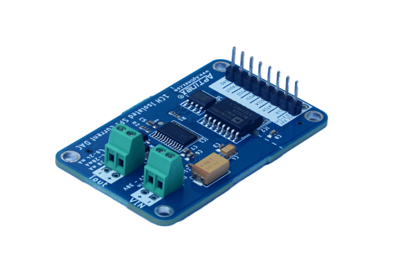
AmpWave DA1C024BS – Isolated Single Channel SPI DAC Module
Aug
How to use Aptinex Isolated SPI DAC module
This galvanically isolated 1 channel SPI DAC module can be used to convert received digital signal into corresponding analog current (Range : 0-24mA, 0-20mA, 4-20mA) output accurately. The module is designed to give one analog current output which is suitable for applications where a single analog signal is required from digital input data. SPI (Serial Peripheral Interface), a common high speed interface is used for communicate between the microcontroller and the DAC module.
Why should you select this module?
- 16-bit resolution – High precision AD5420A DAC ensures smooth and highly accurate signal conversion for detailed and sensitive applications.
- Multi range current output – Software configurable 3 current ranges: 0-24 mA, 4-20mA, 0-20mA for varied applications.
- Galvanic isolation – There’s no direct electrical connection between the input (SPI side) and the output (analog side).. This isolation protects the devices from electrical shocks, voltage surges, and ground loop issues, ensuring safer operation especially in sensitive or hazardous environments.
- SPI interface – Provide high speed, easy and reliable digital communication. It’s work with 3.3V or 5V microcontrollers.
- Power flexibility – Supports 11 -30V supply
- Ideal for process control and automation tasks where reliable and precise analog signaling is crucial.
Connecting the ARDUINO UNO board with the DAC module
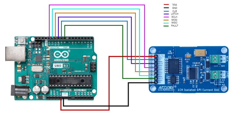
- Vcc pin of DAC to 5V of Arduino uno ; this pin can be connected with both 3.3V or 5V.
-
GND to GND
-
FAULT pin to pin 8 of Arduino
-
CLR pin to pin 9 of Arduino
-
LATCH pin to pin 10 of Arduino
Code lines below define symbolic constants for specific pin numbers on the Arduino board that are connected to various control or status pins of the AD5420 digital-to-analog converter (DAC) module. The values 8, 9, and 10 can be changed to any pin numbers you wish, depending on the specific hardware setup and requirements.
#define AD5420_FAULT 8
#define AD5420_CLEAR 9
#define AD5420_LATCH 10
-
MOSI : pin 11
-
MISO : pin 12
-
SCLK : pin 13
Resolution of Current DAC
Select the current range
dac_ad5420.ad5420_write_ctrl(AD5420_OUTEN | AD5420_REXT | AD5420_0_24_RANGE); //AD5420 intialize (O/P Enable and Range Select)
dac_ad5420.ad5420_write_ctrl(AD5420_OUTEN | AD5420_REXT | AD5420_0_24_RANGE);
dac_ad5420.ad5420_write_ctrl(AD5420_OUTEN | AD5420_REXT | AD5420_0_20_RANGE);
dac_ad5420.ad5420_write_ctrl(AD5420_OUTEN | AD5420_REXT | AD5420_4_20_RANGE);
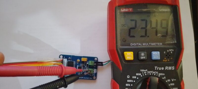
OUTPUTS
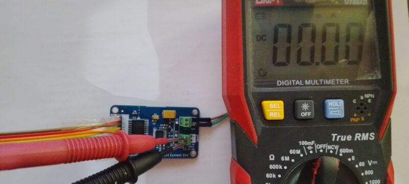
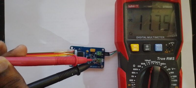
After ensuring the connection of both DAC module and Arduino board the upload the code.
Then connect the multimeter probes to the Iout terminal and measure the current OUTPUT. The input gives the corresponding current output. When the input is ‘0’ DAC will outputs the minimum current value, 0mA/4mA. When the input is ‘G’ DAC will outputs the maximum current, 24mA/20mA.
Code Guide
#include <ad5420.h>
/*
Use the 6 pin SPI connector on arduino DUE board (NOT the ICSP!)
The pin 1 has a white dot behind it.
MOSI:
MISO:
SCLK:
CS: on SPI extended mode can use only PIN 4,10,52 !!!
*/
#define AD5420_FAULT 8
#define AD5420_CLEAR 9
#define AD5420_LATCH 10  //CS

//MOSI ----> Arduino MOSI pin
//MISO----> Arduino MISO pin
//SCLK----->----> Arduino SPI CLK pin

DAC_AD5420 dac_ad5420 = DAC_AD5420(AD5420_LATCH, AD5420_CLEAR, AD5420_FAULT);
uint16_t current = 0;
void setup() {
  Serial.begin(115200); //Serial Com Begin

  Serial.println("AD5420_01_test start!");
  Serial.print("_latch = ");
  Serial.println(dac_ad5420._latch);
  Serial.print("_clear = ");
  Serial.println(dac_ad5420._clear);
  Serial.print("_fault = ");
  Serial.println(dac_ad5420._fault);

  dac_ad5420.begin(); //SPI Communication Begin with AD5420

  delay(100);

  dac_ad5420.ad5420_reset(); //AD5420 Registers rest

  delay(100);


//AD5420 Intialize (O/P Enable and Range Select)
   //AD5420_0_24_RANGE  -----> 0-24mA
  //AD5420_4_20_RANGE  ----->4-20mA
  //AD5420_0_20_RANGE  ----->0-20mA
  dac_ad5420.ad5420_write_ctrl(AD5420_OUTEN | AD5420_REXT | AD5420_0_24_RANGE);


  //    dac_ad5420.ad5420_write_data(0x2000);
  dac_ad5420.ad5420_write_data(current);   //Write 0X0000 ---->O/P Current 0mA , 4mA

}


void loop() {

  Serial.print("Get_Status: ");
  Serial.println(dac_ad5420.ad5420_get_status(), HEX);
  Serial.print("Status_Reg: ");
  Serial.println(dac_ad5420.ad5420_read_reg(AD5420_STATUS_REG), HEX);
  Serial.print("Data_Reg: ");
  Serial.println(dac_ad5420.ad5420_read_reg(AD5420_DATA_REG), HEX);
  Serial.print("Control_Reg: ");
  Serial.println(dac_ad5420.ad5420_read_reg(AD5420_CONTROL_REG), HEX);


  if (Serial.available() > 0) {

    char ch = Serial.read();  // Clean the input buffer

    if (ch == '0') dac_ad5420.ad5420_write_data(0x0000);

    else if (ch == '1') dac_ad5420.ad5420_write_data(0x1000);
    else if (ch == '2') dac_ad5420.ad5420_write_data(0x2000);
    else if (ch == '3') dac_ad5420.ad5420_write_data(0x3000);
    else if (ch == '4') dac_ad5420.ad5420_write_data(0x4000);
    else if (ch == '5') dac_ad5420.ad5420_write_data(0x5000);
    else if (ch == '6') dac_ad5420.ad5420_write_data(0x6000);
    else if (ch == '7') dac_ad5420.ad5420_write_data(0x7000);
    else if (ch == '8') dac_ad5420.ad5420_write_data(0x8000);
    else if (ch == '9') dac_ad5420.ad5420_write_data(0x9000);
    else if (ch == 'A') dac_ad5420.ad5420_write_data(0xA000);
    else if (ch == 'B') dac_ad5420.ad5420_write_data(0xB000);
    else if (ch == 'C') dac_ad5420.ad5420_write_data(0xC000);
    else if (ch == 'D') dac_ad5420.ad5420_write_data(0xD000);
    else if (ch == 'E') dac_ad5420.ad5420_write_data(0xE000);
    else if (ch == 'F') dac_ad5420.ad5420_write_data(0xF000);
    else if (ch == 'G') dac_ad5420.ad5420_write_data(0xFFFF);

  }
  delay(200);
}