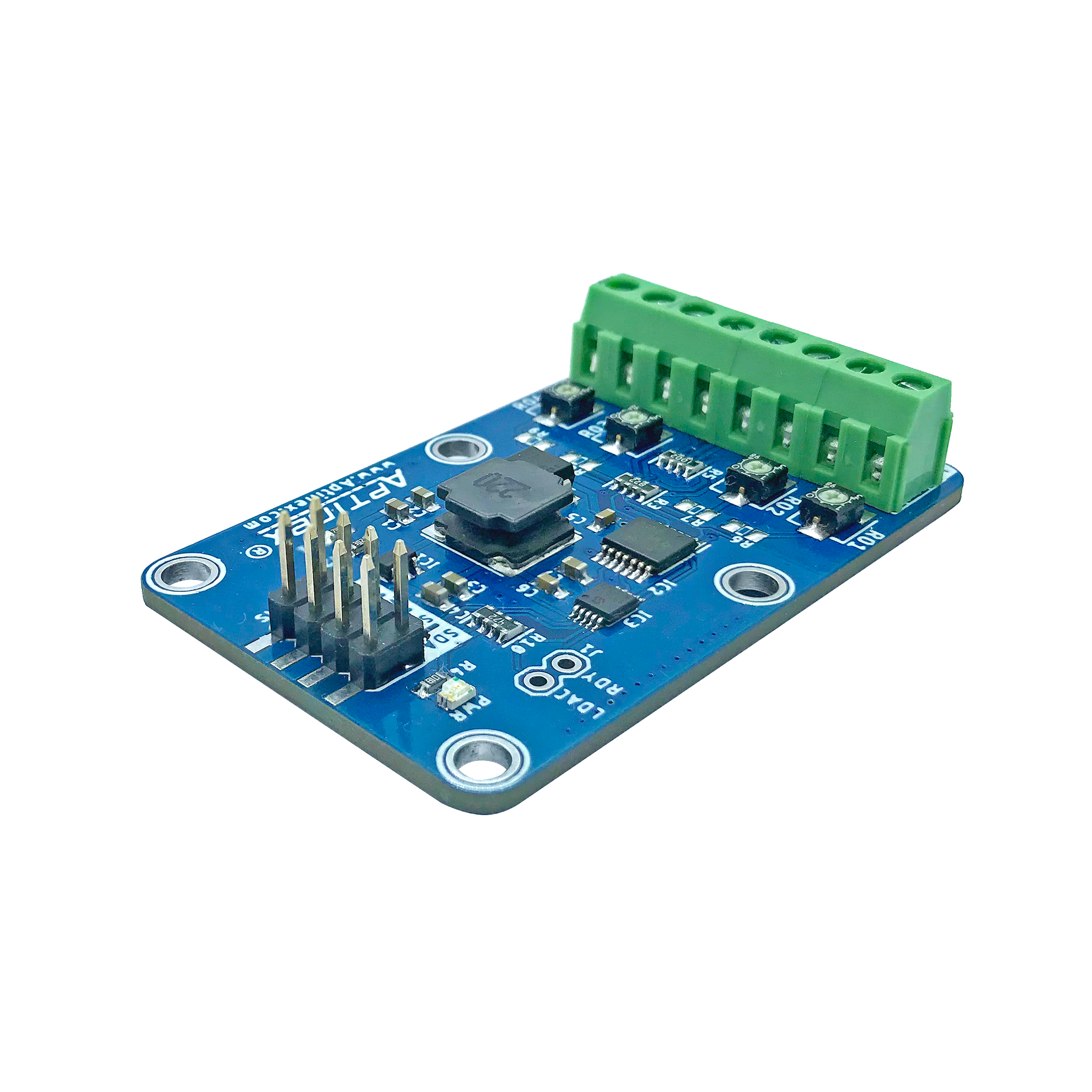
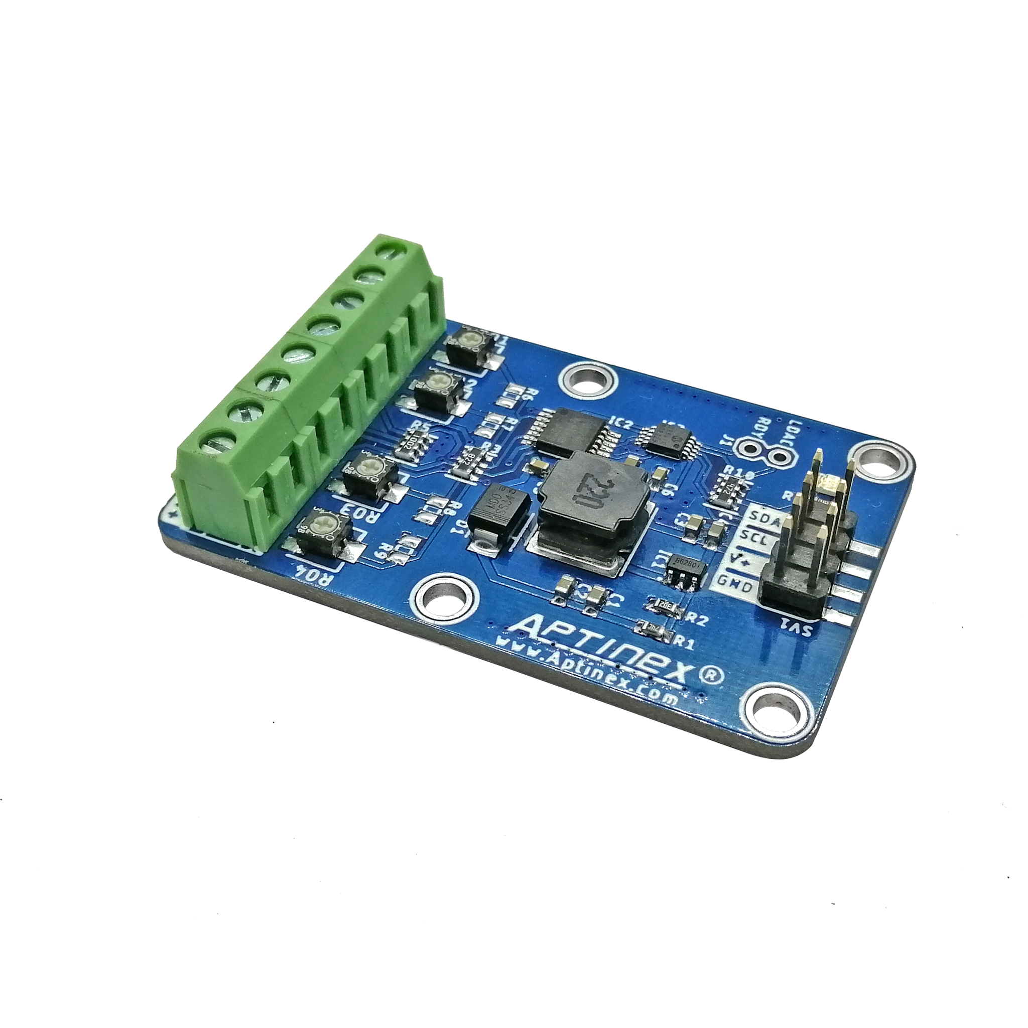
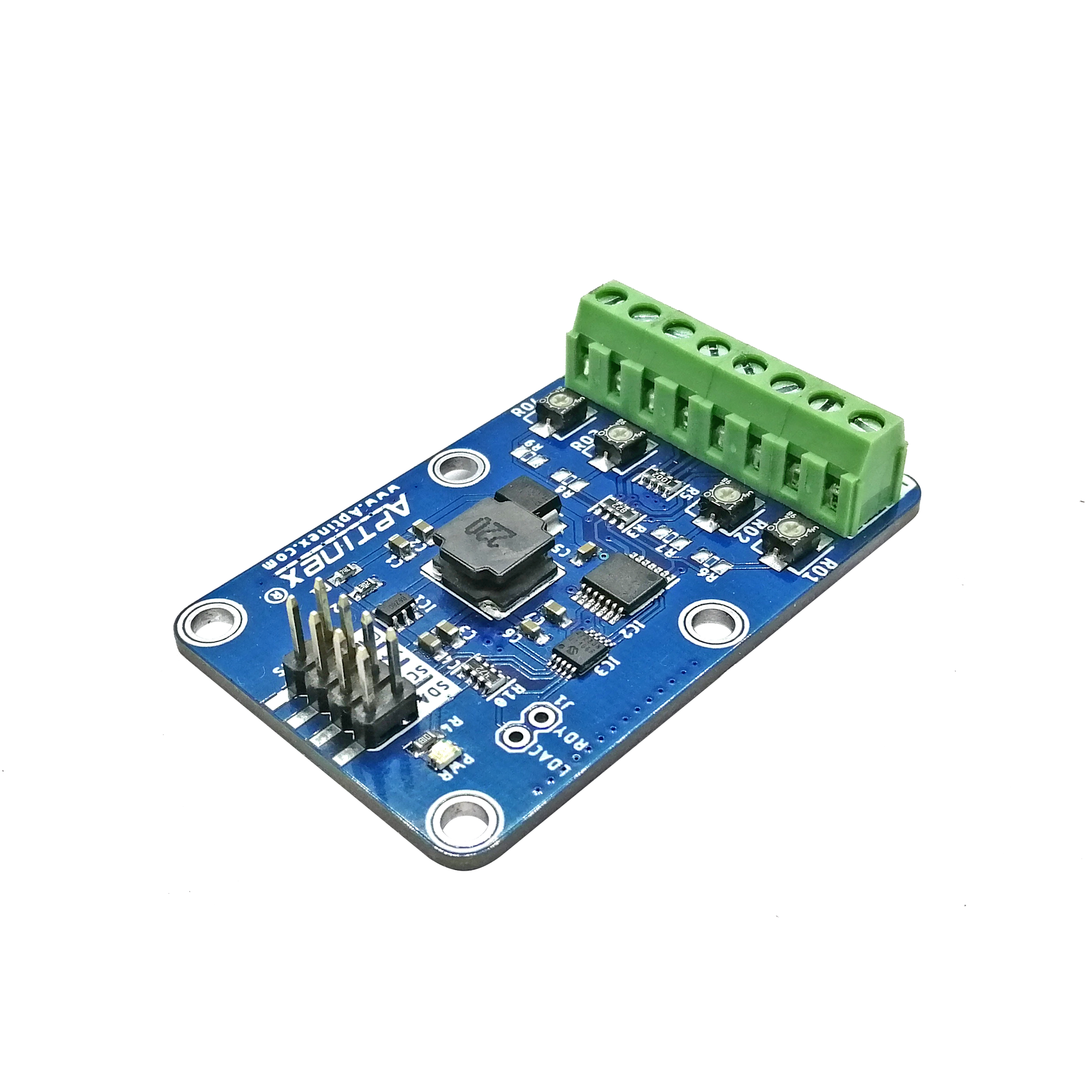
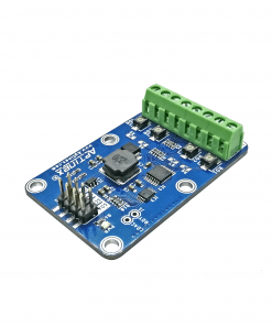
Aptinex 4 Channel DAC Module DA4C010BI I2C Digital to Analog 0-10V MCP4728
$59.90 Original price was: $59.90.$49.90Current price is: $49.90.
16 in stock
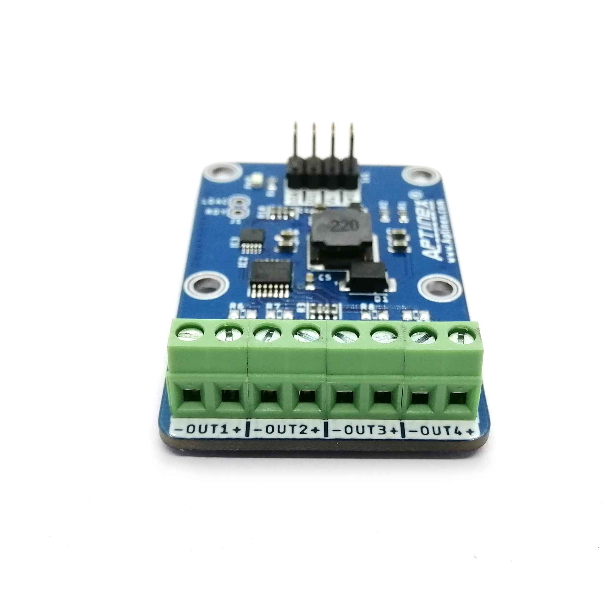
In Data Acquisition, Digital to analog conversion plays a crucial role. A Vast number of devices and equipment types are out there which can be controlled by voltage variation from 0V to 10V. Aptinex DA4C010BI is a perfect solution for this. This module is using I2C as its communication protocol and therefore major microcontrollers or other hardware platforms can use this without much of hustle-bustle. Unlike its single channel predecessor DA1C010BI, DA4C010BI is having the capability of controlling 4 Channels at once.
General Features
- Channels: 4
- PCB Dimension : 3.4cm x 5.4cm
- PCB Color: Blue
- DAC: MCP4728
- Resolution: 12-bit
- Speed; up to 3.4Mbps
- Rail to Rail Operational Amplifier
-
Single-Supply Operation: 2.7V to 5.5V
-
On-Board Non-Volatile Memory (EEPROM)
-
Normal or Power-Down Mode
-
Internal or External Voltage Reference Selection
-
Rail-to-Rail Output
-
Low Power Consumption
-
±0.2 LSB DNL (typical)
-
Address bits: User Programmable to EEPROM
-
Standard (100 kbps), Fast (400 kbps), and High Speed (3.4 Mbps) Modes
-
output setting time: 6 uS
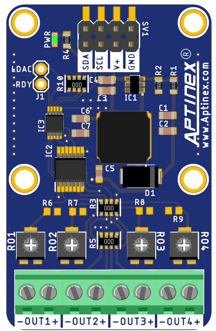
DA4C010BI uses MCP4728 I2C DAC IC with an on-board power boost and rail-to-rail signal amplifier, which takes the 0-5V output of the DAC and covert the same to 0-10V DAC signal. This 0-10V output is programable with a 12-bit resolution which will be having 4096 levels of voltage as output and with an accuracy of ±1%.
In addition, it is possible to share two DACs of this type share the same bus and the I2C address can be changed by plugging or removing the I2C address jumper. If any design is needed more than two of these DAC modules, it is advised to use an I2C multiplexer controller and it will allow you to connect multiple of these DAC modules with one I2C master device.
Three modes of operation are supported.
- standard 100kbps
- fast 400kbps
- high-speed 3.4Mbps
It is possible to interface this module with the following platforms.
- Raspberry Pi
- Arduino
- Onion Omega
- Beaglebone
- Windows,
- Particle Photon
Sample Code
Download Sample | Download Library | Download Change Device Address Sample
| #include <Aptinex_DAC.h> | |
| #include <Wire.h> | |
| Aptinex_4CH_DAC DAC; | |
| void setup(void) { | |
| Serial.begin(115200); | |
| while (!Serial) | |
| delay(10); // will pause Zero, Leonardo, etc until serial console opens | |
| Serial.println(“APTINEX 4CH DAC test!“); | |
| // Try to initialize! | |
| if (!DAC.begin()) { | |
| Serial.println(“Failed to find 4CH DAC Module“); | |
| while (1) { | |
| delay(10); | |
| } | |
| } | |
| Serial.println(“4CH DAC Module Found!“); | |
| /* | |
| * @param channel The channel to update | |
| * @param new_value The new value to assign | |
| * @param new_vref Optional vref setting – Defaults to `MCP4728_VREF_VDD` | |
| * @param new_gain Optional gain setting – Defaults to `MCP4728_GAIN_1X` | |
| * @param new_pd_mode Optional power down mode setting – Defaults to | |
| * `MCP4728_PD_MOOE_NORMAL` | |
| * @param udac Optional UDAC setting – Defaults to `false`, latching (nearly). | |
| * Set to `true` to latch when the UDAC pin is pulled low | |
| * | |
| */ | |
| // Vref = MCP_VREF_VDD, value = 0, 0V | |
| DAC.setChannelValue(MCP4728_CHANNEL_A, 0); | |
| // value is vref/2, with 2.048V internal Vref and 1X gain | |
| // = 2.048/2 = 1.024V | |
| DAC.setChannelValue(MCP4728_CHANNEL_B, 2048, MCP4728_VREF_INTERNAL, MCP4728_GAIN_1X); | |
| // value is vref/2, with 2.048V internal vref and *2X gain* | |
| // = 4.096/2 = 2.048V | |
| DAC.setChannelValue(MCP4728_CHANNEL_C, 2048, MCP4728_VREF_INTERNAL, MCP4728_GAIN_2X); | |
| // value is vref/2, Vref is MCP4728_VREF_VDD(default), the power supply | |
| // voltage (usually 3.3V or 5V) For Vdd/Vref = 5V, voltage = 2.5V For 3.3V, | |
| // voltage = 1.65V Values will vary depending on the actual Vref/Vdd | |
| DAC.setChannelValue(MCP4728_CHANNEL_D, 2048); | |
| DAC.saveToEEPROM(); | |
| } | |
| void loop() { delay(1000); } |
| import adafruit_mcp4728 | |
|
import busio
|
|
|
MCP4728_DEFAULT_ADDRESS = 0x60
|
|
|
i2c = busio.I2C(3,2)
|
|
|
mcp4728 = adafruit_mcp4728.MCP4728(i2c, adafruit_mcp4728.MCP4728_
|
|
|
def set_dac_voltage (channel, voltage):
|
|
|
if channel == ‘A’:
|
|
|
mcp4728.channel_a.value = voltage
|
|
|
if channel == ‘B’:
|
|
|
mcp4728.channel_b.value = voltage
|
|
|
if channel == ‘C’:
|
|
|
mcp4728.channel_c.value = voltage
|
|
|
if channel == ‘D’:
|
|
|
mcp4728.channel_d.value = voltage
|
|
|
print(“***MCP4728 DAC MODULE TEST CODE***”)
|
|
|
print(“Enter channel (A, B, C, or D) and voltage value (0-10V) separated by a space.”)
|
|
|
print(“Example: A 5.00”)
|
|
|
print(“n”)
|
|
|
while True:
|
|
|
user_input = input()
|
|
|
input_list = user_input.split()
|
|
|
if len(input_list) == 2:
|
|
|
channel = input_list[0].upper()
|
|
|
voltage = float(input_list[1])
|
|
|
if voltage >= 0 and voltage <= 10:
|
|
|
cal_voltage= int ((65535/1000)*100*voltage)
|
|
|
set_dac_voltage(channel, cal_voltage)
|
|
|
print(f”DAC Channel {channel} set to {voltage}V”)
|
| Weight | 50 g |
|---|

