AM1815 (AB1815) Ultra-Low Power RTC Module (Communication Protocol: I2C)
$29.90
AM1815 based low power real-time clock module I2C
The “Aptinex Ultra-Low Power RTC” module provides an easy real time clock solution for applications such as utility meters, medical electronics, communication equipment and multitude of other devices. Since the module requires significantly lower power than most real time clocks available in the market (14nA – 55nA) it is extremely suitable for applications that require very low power consumption. The RTC includes various features that can be used as required by the implementation, making it a versatile component and a desirable choice. The module can be ordered either with SPI or I2C communication functionalities.
The Aptinex Ultra-Low Power RTC Module includes the AM1815 IC by Ambiq Micro which is an ultra-low power IC which includes a highly sophisticated feature set. This RTC requires significantly less power than any other industrial alternatives due to the innovative power optimization technologies provided by Ambiq Micro. The AM1815 chip on the module provides minimal power consumption, complete RTC functions which includes battery backup, programmable counters, alarms for timers and watchdog functions, and I2C serial communication capabilities. These features of integrated chip including its integrated power switch and its sophisticated sleep functionalities makes the module suitable for be used as a supervisory component for a host microcontroller-based system.
Features
- Ultra-low supply current at 3V:
- 14 nA (with RC oscillator)
- 22 nA (with RC oscillator and autocalibration)
- 55 nA (with crystal oscillator)
- Baseline timekeeping features:
- Crystal oscillator with integrated load capacitor/resistor
- Counters and alarm capabilities (includes automatic leap year calculation)
- Countdown timer with repeat functions
- Advanced timekeeping features:
- Power optimized RC oscillator
- Crystal and RC calibration
- Automatic calibration of RC to crystal oscillator
- Watchdog timer with hardware reset
- 256 bytes of general-purpose RAM
- Power management features:
- Integrated power switch for off-chip components
- System sleep manager for managing host processor wake/sleep states
- External reset signal monitor and interrupt monitor
- Programmable low battery detection threshold and analog voltage comparator
- I2C or SPI serial interfaces available
- Operating voltage: (1.5 – 3.6 V)
- Clock and RAM retention voltage: 1.5 – 3.6 V
- Operating temperature: –40°C – 85 °C
Included Hardware
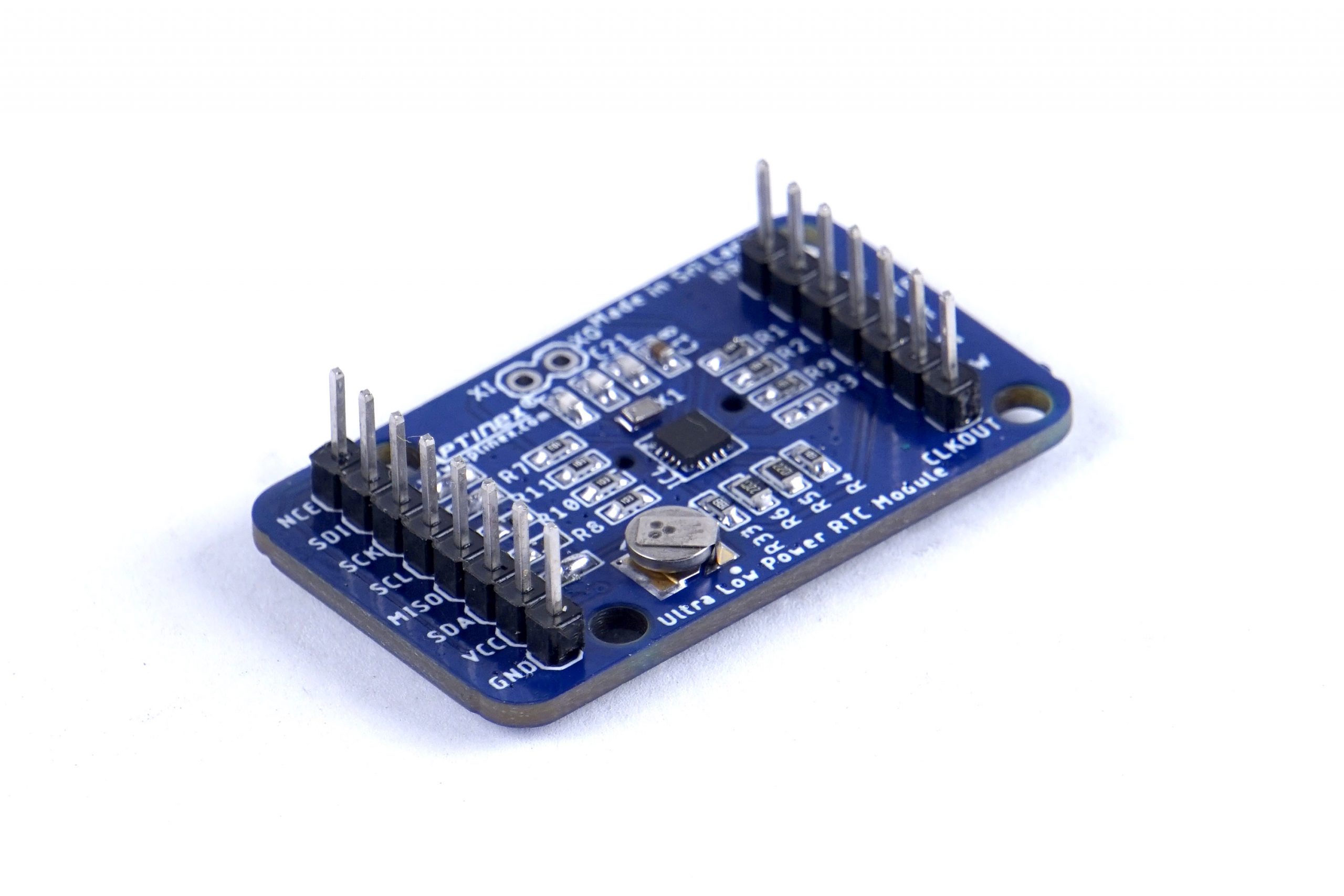
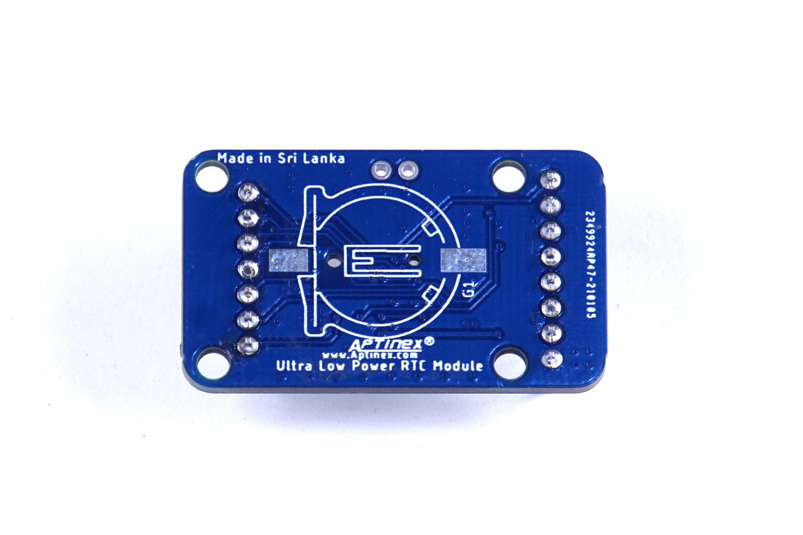
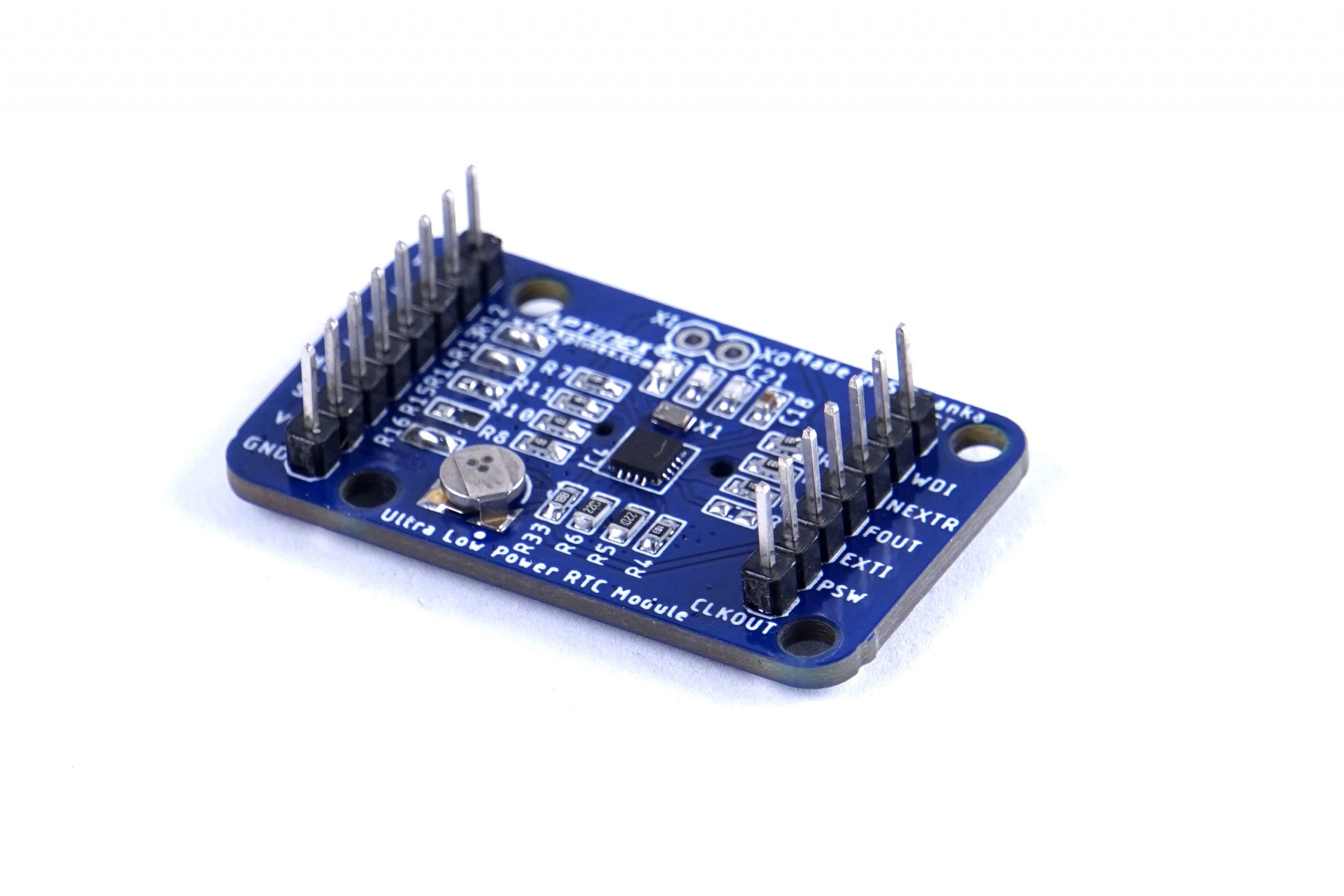
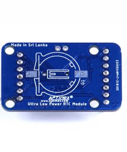
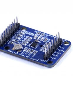
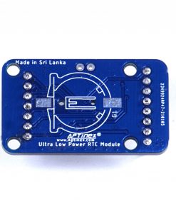
Component is shipped fully packaged and as represented in the product images. Included within the package the user will find; the RTC module with one 1×8 and one 1×7-pin breakaway 0.1” inch, straight or right-angled male headers.
Connection Diagram
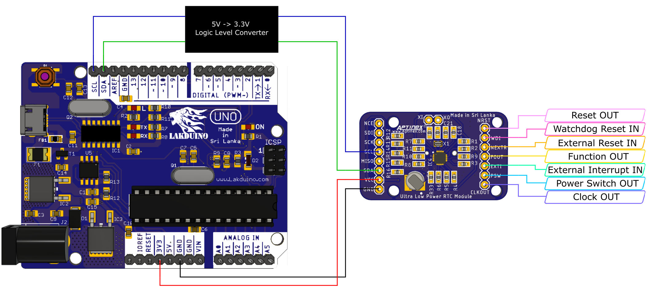
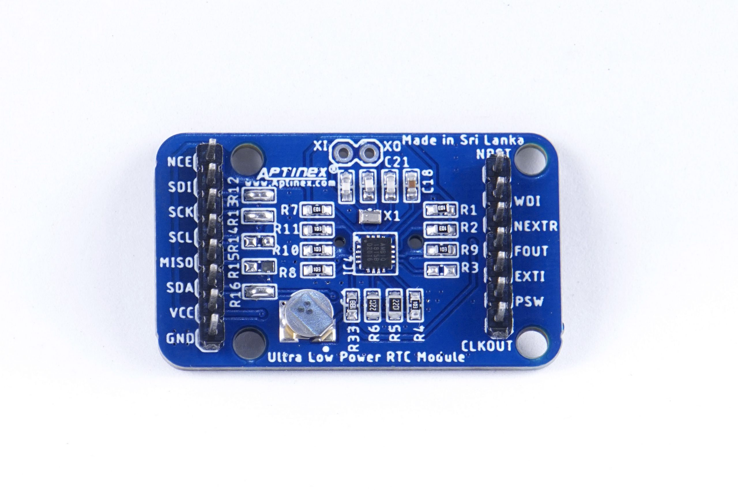
Pinout
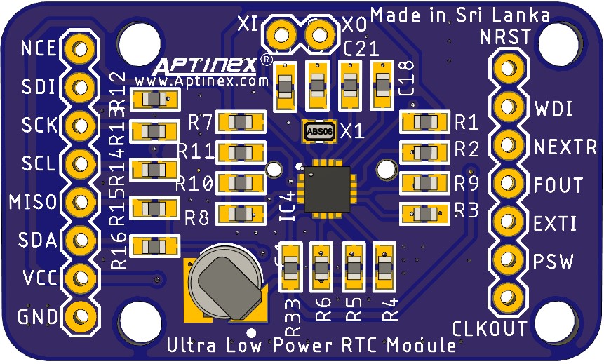
RTC PCB Top View
| PIN | PIN TYPE | DESCRIPTION |
|---|---|---|
| LEFT SIDE PINS | ||
| NCE | Input | -Reserved for SPI interface parts- |
| SDI | Input | -Reserved for SPI interface parts- |
| SCK | Input | -Reserved for SPI interface parts- |
| SCL | Input | I/O interface clock connection. Provides the SCL input for I2C interface parts. |
| MISO | Input | -Reserved for SPI interface parts- |
| SDA | Input | I/O interface I2C data connection. |
| VCC | Power | Primary power connection. |
| GND | Power | Ground connection. |
| RIGHT SIDE PINS | ||
| NRST | Output | External reset output connection. It is an open drain output. |
| WDI | Input | Watchdog Timer reset input connection. It may also be used to generate an External 2 interrupt. It must not be left floating or the RTC may consume higher current. It must be connected directly to either VCC or GND if not used. |
| NEXTR | Input | External reset input connection. It must not be left floating or the RTC may consume higher current. It must be connected directly to either VCC or GND if not used. |
| FOUT | Output | Primary interrupt output connection. This pin is an open drain output. It should be connected to the host device and is used to indicate when the RTC can be accessed via the serial interface. |
| EXTI | Input | External interrupt input connection. It may be used to generate an External 1 interrupt. It must not be left floating or the RTC may consume higher current. It must be connected directly to either VCC or GND if not used. |
| PSW | Output | Secondary interrupt output connection. It is an open drain output. This pin can be left floating if not used. |
| CLKOUT | Output | Square Wave output connection. It is a push-pull output and may be configured to generate one of two signals. |
*for further information refer to the AM18X5 datasheet provided by Ambiq Micro.

