
Uncategorized
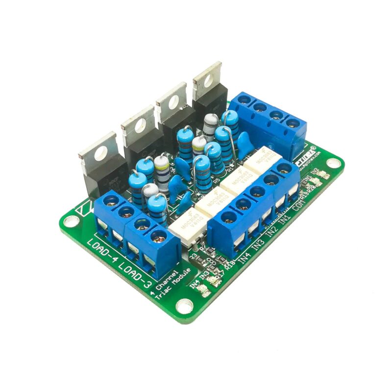
Aptinex Four Channel Triac Module
Aug
The Module makes it easy to control AC, high-power devices using any microcontroller.
Things used in this project
Hardware components
- Aptinex Four Channel Traic Module x 1
- Lakduino UNO x 1
Software apps and online services
Story
APTINEX Four Channel Triac Module, is capable of controlling AC devices using its channels simultaneously with the aid of any microcontroller. Why would you choose a traic version over a relay? Traics have a longer lifetime than relays, as they are built of semiconductors. An optocouler is used in the module to provide isolation between high and low voltages. What protects the circuit when it is powered directly from the AC supply? MOV (metal-oxide vasristor) protection is used to protect against high voltage surges. A Voltage Snubber is also used for effective performance and device protection.
- Traic: BT139
- Four Digital Inputs
- Phototraic Driver: MOC3061/ MOC3063
- Dimming: Not supported (On/ Off only)
- Can connect heat sinks for high power loads
- Capable of controlling home appliances (Lamps, Fans, Electric Ovens, Etc.)
- Temperature, light and electric gate controlling
- E. M. Contactors
Connection Diagram
Test
Once the above connections are complete, upload the following code to Arduino.
int BULB1 = 2;
int BULB2 = 3;
int BULB3 = 4;
int BULB4 = 5;
int DELAY_1 = 1000;
int DELAY_2 = 1000;
int DELAY_3 = 1000;
int DELAY_4 = 1000;


void setup()
{
  pinMode(BULB1, OUTPUT);
  pinMode(BULB2, OUTPUT);
  pinMode(BULB3, OUTPUT);
  pinMode(BULB4, OUTPUT);
}

void loop()
{
  first_bulb();
  delay(DELAY_1);
  second_bulb();
  delay(DELAY_2);
  third_bulb();
  delay(DELAY_3);
  fourth_bulb();
  delay(DELAY_4);
}

void first_bulb()
{
  digitalWrite(BULB1, HIGH);
  digitalWrite(BULB2, LOW);
  digitalWrite(BULB3, LOW);
  digitalWrite(BULB4, LOW);
}

void second_bulb ()
{
  digitalWrite(BULB1, LOW);
  digitalWrite(BULB2, HIGH);
  digitalWrite(BULB3, LOW);
  digitalWrite(BULB4, LOW);
}

void third_bulb()
{
  digitalWrite(BULB1, LOW);
  digitalWrite(BULB2, LOW);
  digitalWrite(BULB3, HIGH);
  digitalWrite(BULB4, LOW);
}
void fourth_bulb()
{
  digitalWrite(BULB1, LOW);
  digitalWrite(BULB2, LOW);
  digitalWrite(BULB3, LOW);
  digitalWrite(BULB4, HIGH);
}
Your circuit should work as follows,