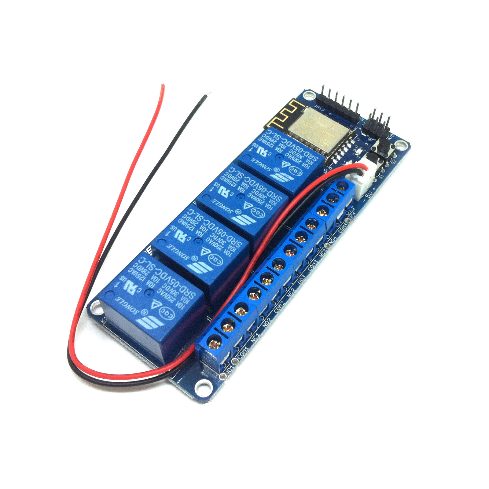
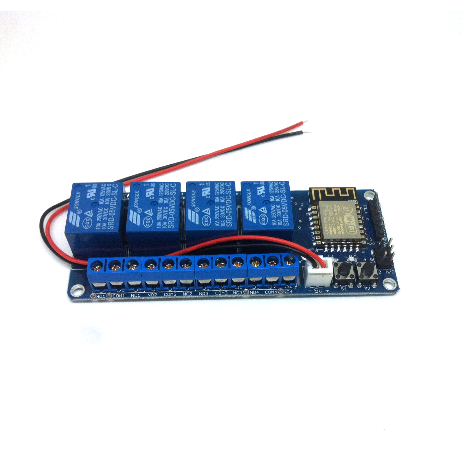
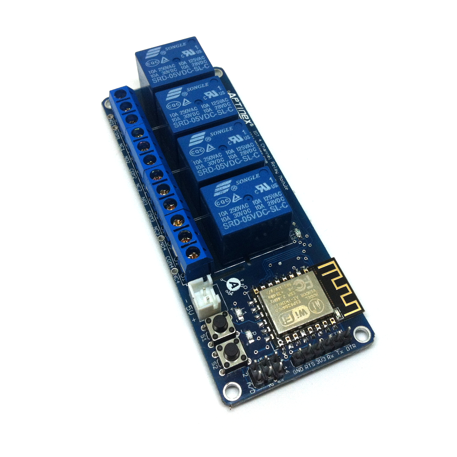
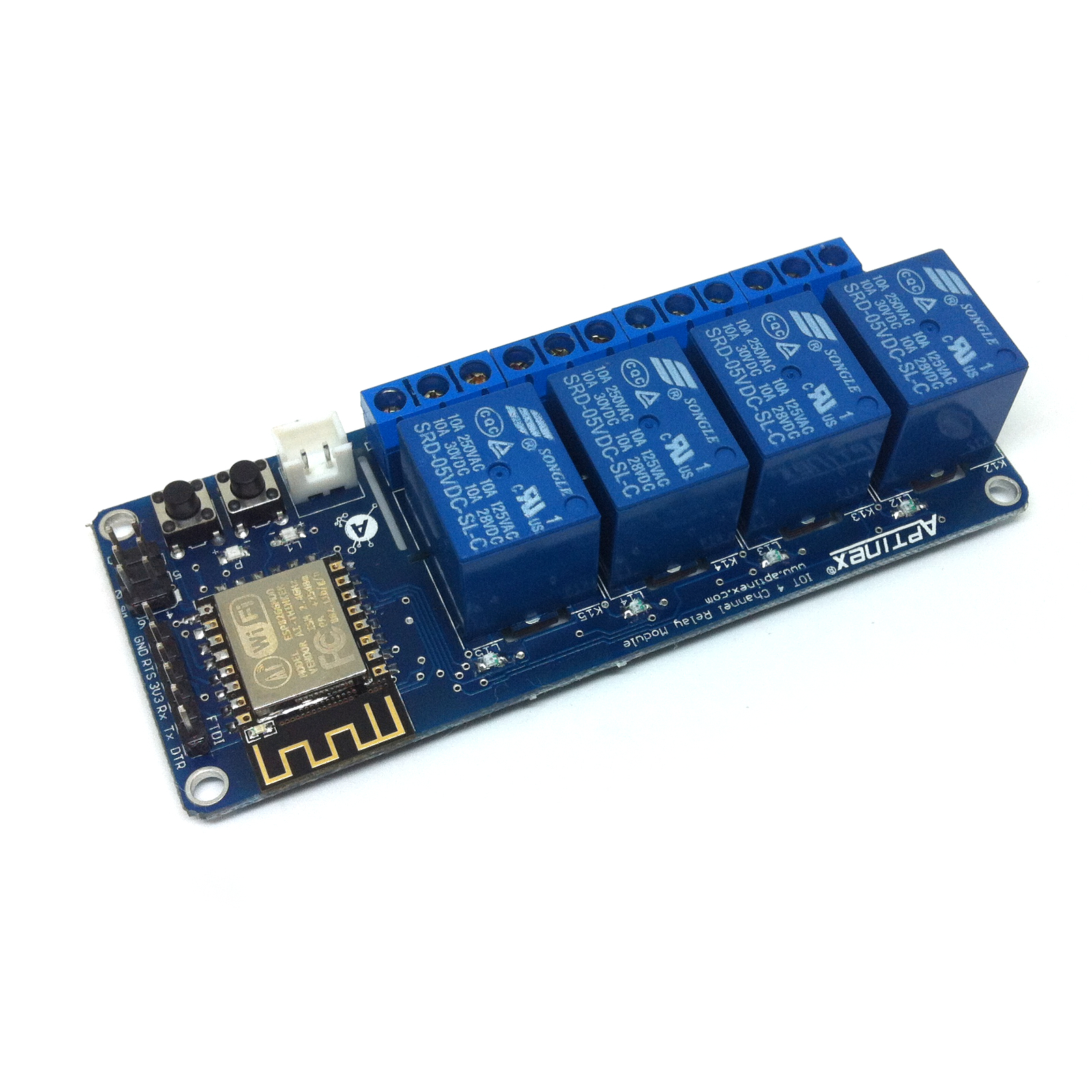
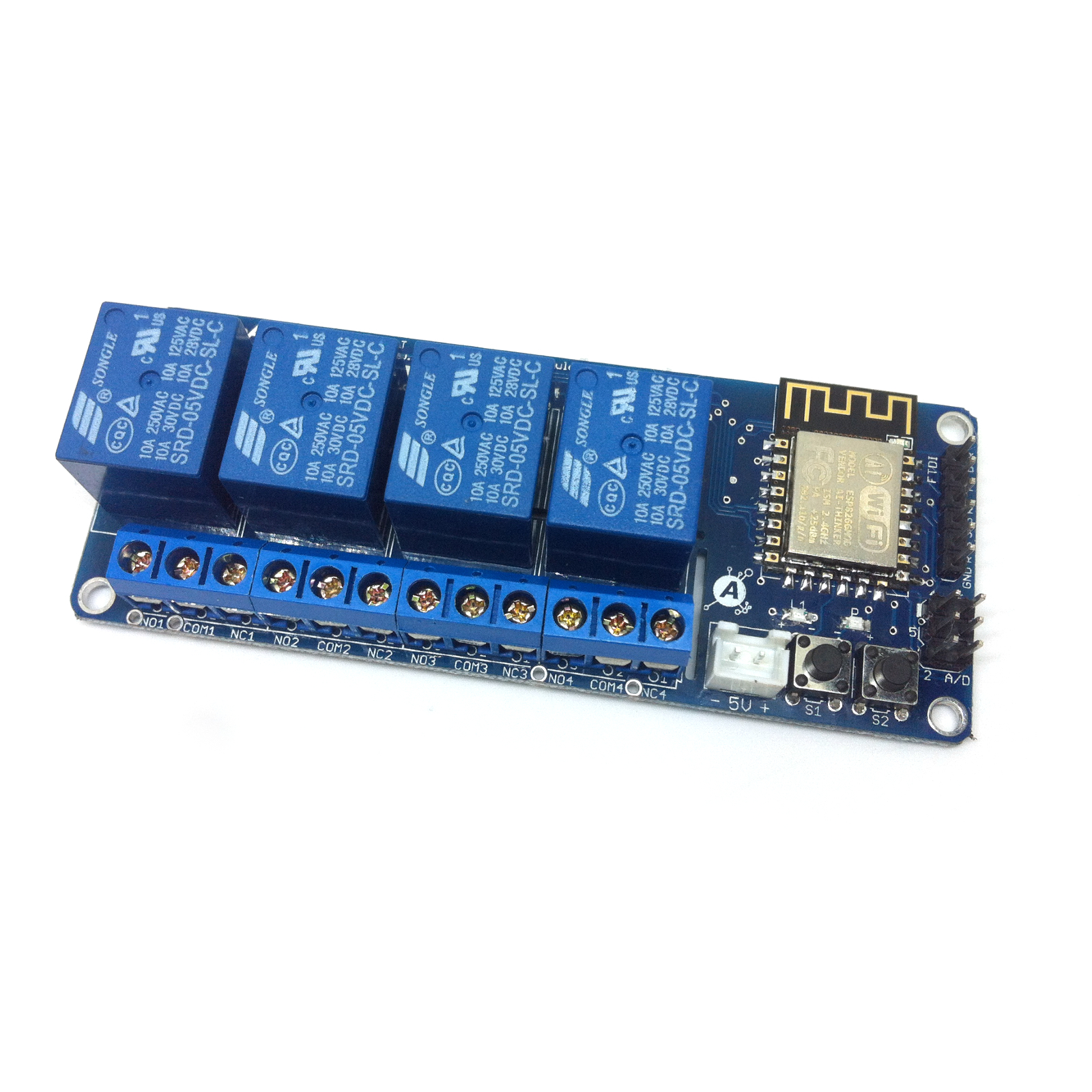
Aptinex IOT RelayNode RN4CE8 (ESP8266, 4CH)
$17.50
ESP8266 Based ,MQTT Enabled 4 Channel IOT Relay Module
14 in stock
SKU: APT023
Categories: IOT, RelayNODE, Wi-Fi
Tags: #ai, #arduinoproject, #artificialintelligence, #automation, #bhfyp, #bigdata, #blockchain, #business, #cloud, #cybersecurity, #data, #datascience, #electronics, #engineering, #esp, #g, #innovation, #internetofthings, #machinelearning, #o, #programming, #raspberrypi, #security, #smarthome, #software, #tech, #technology, 4 Channel, Aptinex, arduino, ESP8266, iot, MQTT, Relay, RelayNode, Relays, RN4CE8, robotics, Wi-Fi, WIFI
GTIN: 045916099250
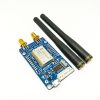
Aptinex IOT 4 channel relay module is the first IOT related device manufactured by Aptinex along with many other oncoming IOT devices. The main objective of Team Aptinex in designing this was to ease the controlling applications related to smart home ,lighting etc. This unit is based on famous wifi module ESP8266 and is having a pre-flashed firmware plus a user interface for controlling relays and changing settings.
If needed, instead of using already flashed firmware,custom made firmware can also be programmed.
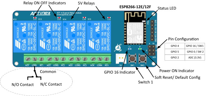
General Features
- WIFI Engine : ESP8266 – ESP12F
- Supply voltage : 5V
- PCB Dimension : 4.0cm x 10.0cm
- Relays
- Number of Relays : 4
- Relay Manufacturer – Songle
- Relay Coil Voltage : 5V
- Relay Contact Ratings : 10A/250VAC
- Associated GPIOS with the relays (Relays to ESP8266 GPIOs mapping)
- Relay 1 (K12) : GPIO 12
- Relay 2 (K13) : GPIO 13
- Relay 3 (K14) : GPIO 14
- Relay 4 (K15) : GPIO 15
- Associated GPIOs with the switches (Switches to ESP8266 GPIO Mapping )
- SW2/L1 – GPIO 16
- Modes of operation : 2
- Access Point mode (AP Mode)
- Default mode
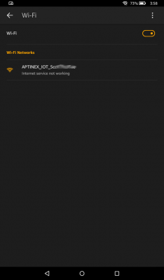
- ESP8266 acts like an access point and devices can connect to it.
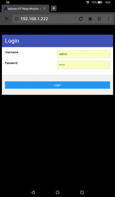
- Initial IP:192.168.1.222
- Password : No Password ( Blank)
- SSID : APTINEX_IOT_(MAC ADDRESS )
- Station Mode (ST Mode)
- ESP8266 acts like a device and will connect to an Access point
- Access Point mode (AP Mode)
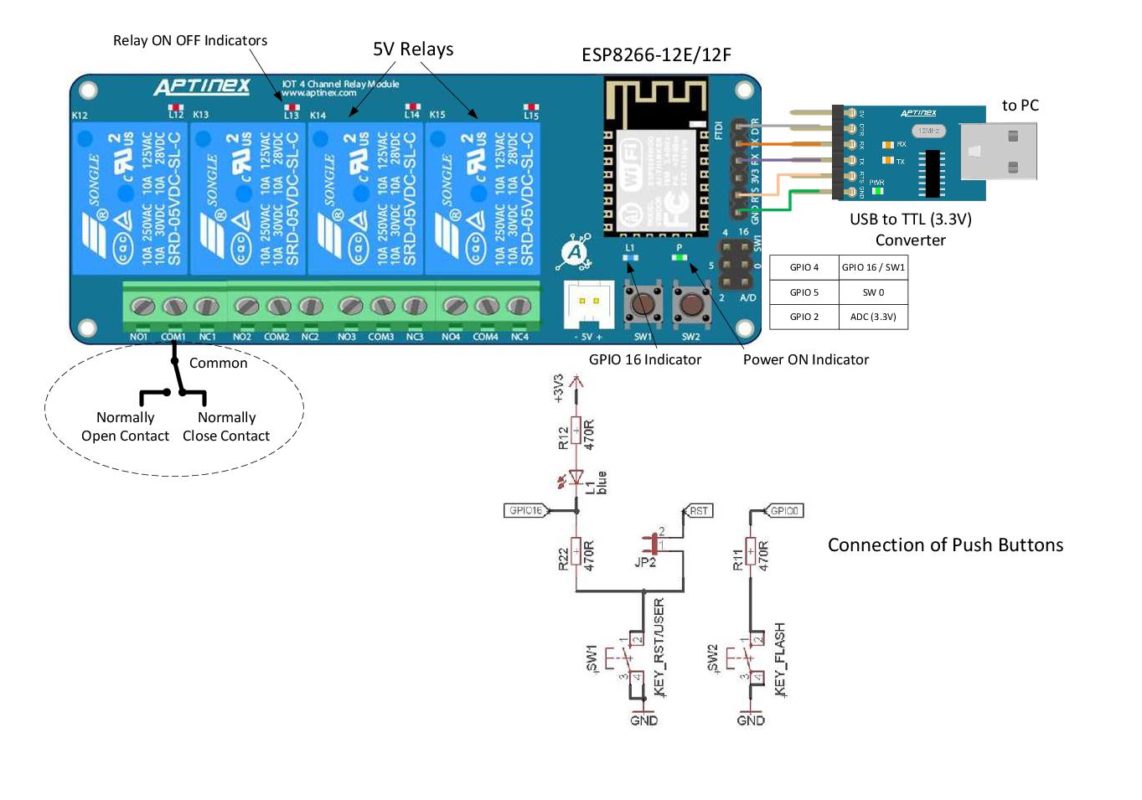
- Modes of relay controlling – 3
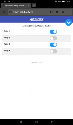
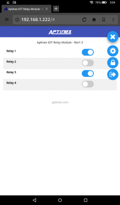
- Using the inbuilt web UI (Can be accessed via http://192.168.1.222)
- Manually Passing commands via URL Supply voltage : 5V
- Relay 1 – On :http://192.168.1.222/set?gpio=12&value=1
- Relay 1 – Off :http://192.168.1.222/set?gpio=12&value=0
- Relay 2 – On :http://192.168.1.222/set?gpio=13&value=1
- Relay 2 – Off :http://192.168.1.222/set?gpio=13&value=0
- Relay 3 – On : http://192.168.1.222/set?gpio=14&value=1
- Relay 3 – Off :http://192.168.1.222/set?gpio=14&value=0
- Relay 4 – On :http://192.168.1.222/set?gpio=15&value=1
- Relay 4 – Off :http://192.168.1.222/set?gpio=15&value=0
- Via a MQTT Host/Broker
- The unit will be serving as a MQTT client
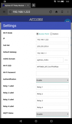
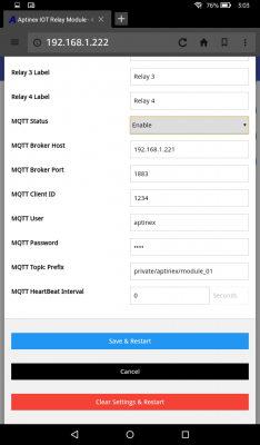
- MQTT settings can be set at the settings page of the web UI
- MQTT Status : Can enable or disable MQTT Mode
- MQTT Broker Host : IP address of the MQTT broker . Can be local or public. But if the host is public ,it may be needed to add a NAT (Network Adrress Translation) at the router depending on your scenario.
- MQTT Broker Port : The port that is goint to be used for MQTT communication , check with your MQTT Broker
- MQTT Client ID: Unique id for the client to be connected to the MQTT Broker
- MQTT Username / Password : These are for the client to be authenticated at the MQTT Broker
- MQTT Heartbeat Interval : MQTT keepalive time ,which the client commits by sending regular PING Request messages to the broker


Applications
- Home Automation
- Industrial IOT Applications
- Lighting Controls
| Weight | 150 g |
|---|---|
| UPC |
Related products
LuminaDALI
$125.00
$39.90
$39.90

