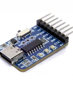
I2C Isolator – ISO1540D
$14.50
17 in stock
Aptinex I2C Isolator – ISO1540D
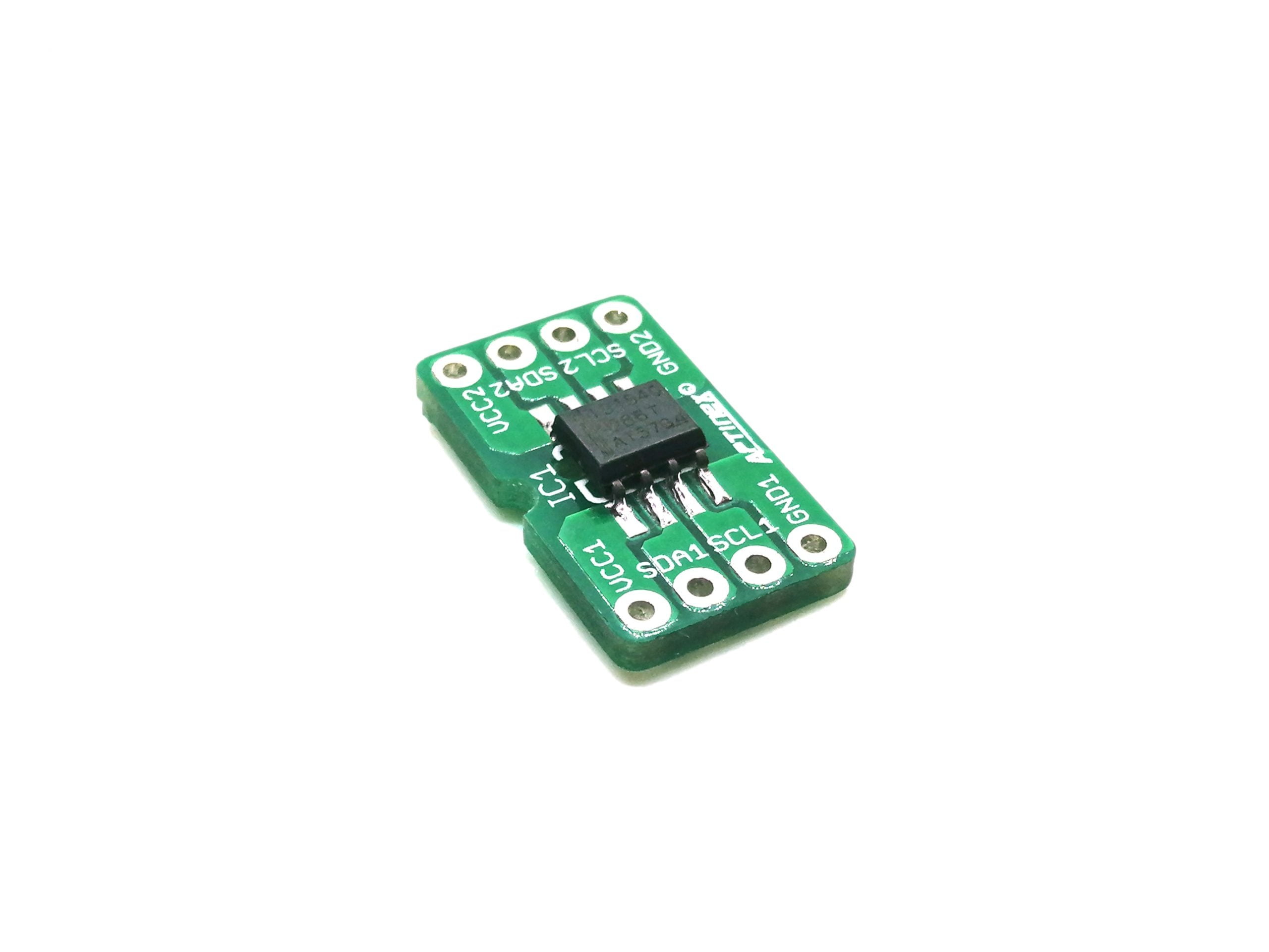
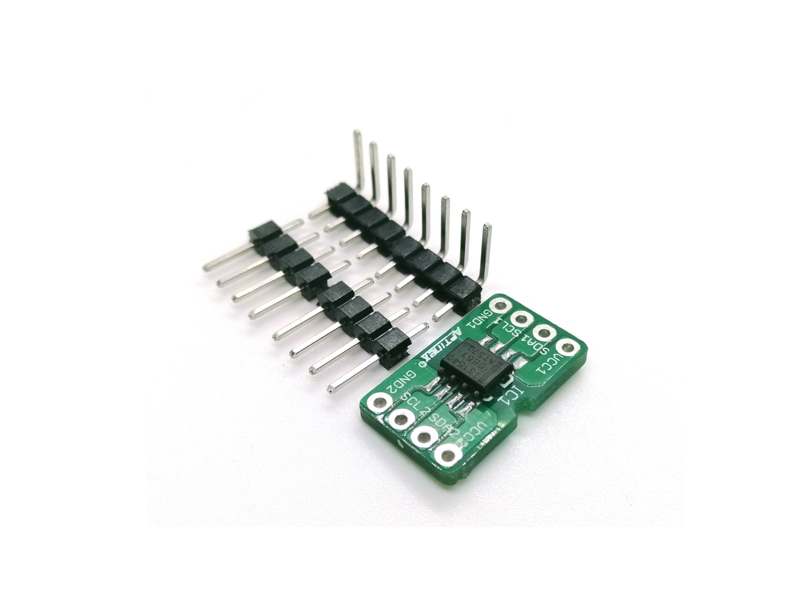
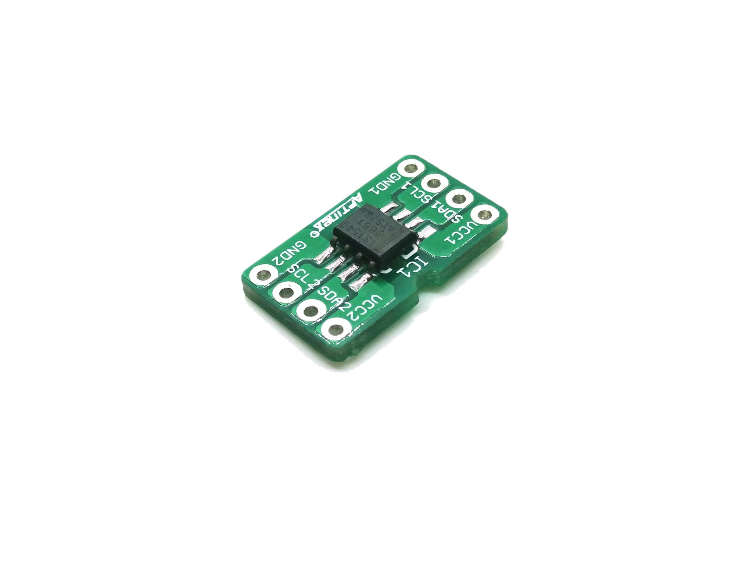
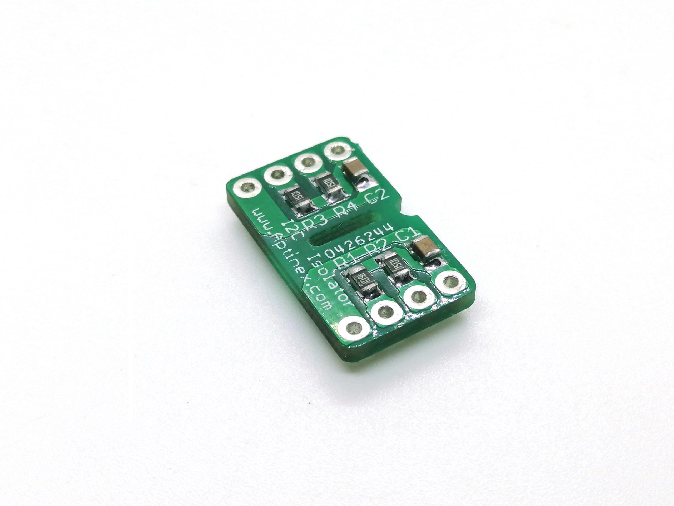
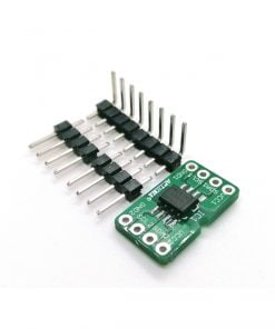
Aptinex I2C Isolator module comprises a ISO1540, which is a low-power, bidirectional isolating chip for I2C interfaces. This is a low cost solution for isolating your I2C devices in both testing and production environments.
ISO1540
The ISO1540 and ISO1541 devices are low-power, bidirectional isolators that are compatible with I2C interfaces. These devices have logic input and output buffers that are separated by Texas Instruments Capacitive Isolation technology using a silicon dioxide (SiO2) barrier. When used with isolated power supplies, these devices block high voltages, isolate grounds, and prevent noise currents from entering the local ground and interfering with or damaging sensitive circuitry.
Features
- Isolated bidirectional, I2C compatible, communication
- Supports up to 1-MHz operation
- 3-V to 5.5-V supply range
- Open-drain outputs With 3.5-mA Side 1 and 35-mA Side 2 sink current capability
- –40°C to +125°C operating temperature
- ±50-kV/µs transient immunity (Typical)
- HBM ESD protection of 4 kV on all pins;
8 kV on bus pins - Safety-related certifications:
- 4242-VPK isolation per DIN VDE V 0884-11:2017-01
- 2500-VRMS isolation for 1 minute per UL 1577
- CSA approval per IEC 60950-1 and IEC 62368-1 end equipment standards
- CQC basic insulation per GB4943.1-2011
What is I2C ??
I2C (Also pronoused as I-squared-C ) is a synchronous, multi-master, multi-slave, packet switched, single-ended serial protocol for two-wire interfaces for connecting low-speed devices such as microcontrollers, EEPROMs, A/D or D/A converters, I/O interfaces and many other similar peripherals in embedded systems. Originally founded by Philips Semiconductors, but nowadays used by almost all IC manufacturers.
Each I2C slave is in the need of an address which must allocated by NXP (former Philips semiconductors).

I2C bus is much famous due to its simplicity to use. It is Ok to have more than one master, only upper bus speed is defined and byusing only two wires with pull-up resistors it is capable of connecting almost unlimited number of I2C devices as needed.
If correct Start and Stop Conditions can be generated (in addition to functions for reading and writing a byte), I2C can even be used with slower microcontrollers with general purpose I/Os.
Each and every slave device is to be having its unique slave address. 8 bit packets are used for transfer from and to master device.These simple requirements and Only two i/O pins and a set of simple I2C routines are neede for sending and recieve I2C commands and data.
A clock frequency of 100 KHZ is defined by the initial I2C specification but later increased to the clock frequency of 400kHz and named “Fast Mode” . An high speed mode of 3.4 MHz and Ultra fast mode of 5MHz already exists and used for special circumstances .
I2C Interface
Only 2 wires are used in I2C , Serial Clock (SCL) and Serial Data (SDA) and both of them are in the need of pulled high with a resister to +VDD. For connecting two I2C buses with different voltages I2C level shifters are used.
I2C Addresses
Transfer of 8 bits is used in basic I2C communication and each slave is to be having a 7 bit address which should be unique on the bus. Fixed I2C addresses are found in some devices while others keep few address lines to determine the lower bits of the I2C address which is very easy for providing all the I2C devices in the bus with their unique addresses. There are some devices with 10 bit addresses as allowed by the specification.
In 7 bit addresses, address is represented from bits 7 to 1 while bit 0 is reserved for signaling reading from or writing to the device. If bit 0 is set to 1 then the master device will read from the slave I2C device and if the bit 0 is cleared the master device will write data to the slave device.
No address will not be needing for the master device as it will be generating the Clock via SCL and addresses individual I2C slave devices.
I2C Protocol

In normal state both lines (SCL and SDA) are high. The communication is initiated by the master device. It generates the Start condition (S) followed by the address of the slave device (B1). If the bit 0 of the address byte was set to 0 the master device will write to the slave device (B2). Otherwise, the next byte will be read from the slave device. As soon as all the reading and writing bytes are done (Bn), the Stop condition (P) is generated by the master device. This is for signaling other devices on the bus that the communication is completed and another device may be using the bus.
Majority of I2C devices support repeated start condition which means that before the communication ends with a stop condition, master device is able to repeat start condition with address byte and change the mode from writing to reading.
Conclusion
I2C bus is used by many integrated circuits and is simple to implement. Any microcontroller can communicate with I2C devices even if it has no special I2C interface. I2C specifications are flexlible – I2C bus can communicate with slow devices and can also use high speed modes to transfer large amounts of data. Because of many advantages, I2C bus will remain as one of the most popular serial interfaces to connect integrated circuits on the board.
Related products
Data Conversion
Power Control
Data Conversion

