AmpWave DA1C024BS – Isolated Single Channel SPI Multi-Range Current DAC Module AD5420A
$49.00 Original price was: $49.00.$39.00Current price is: $39.00.
30 in stock (can be backordered)
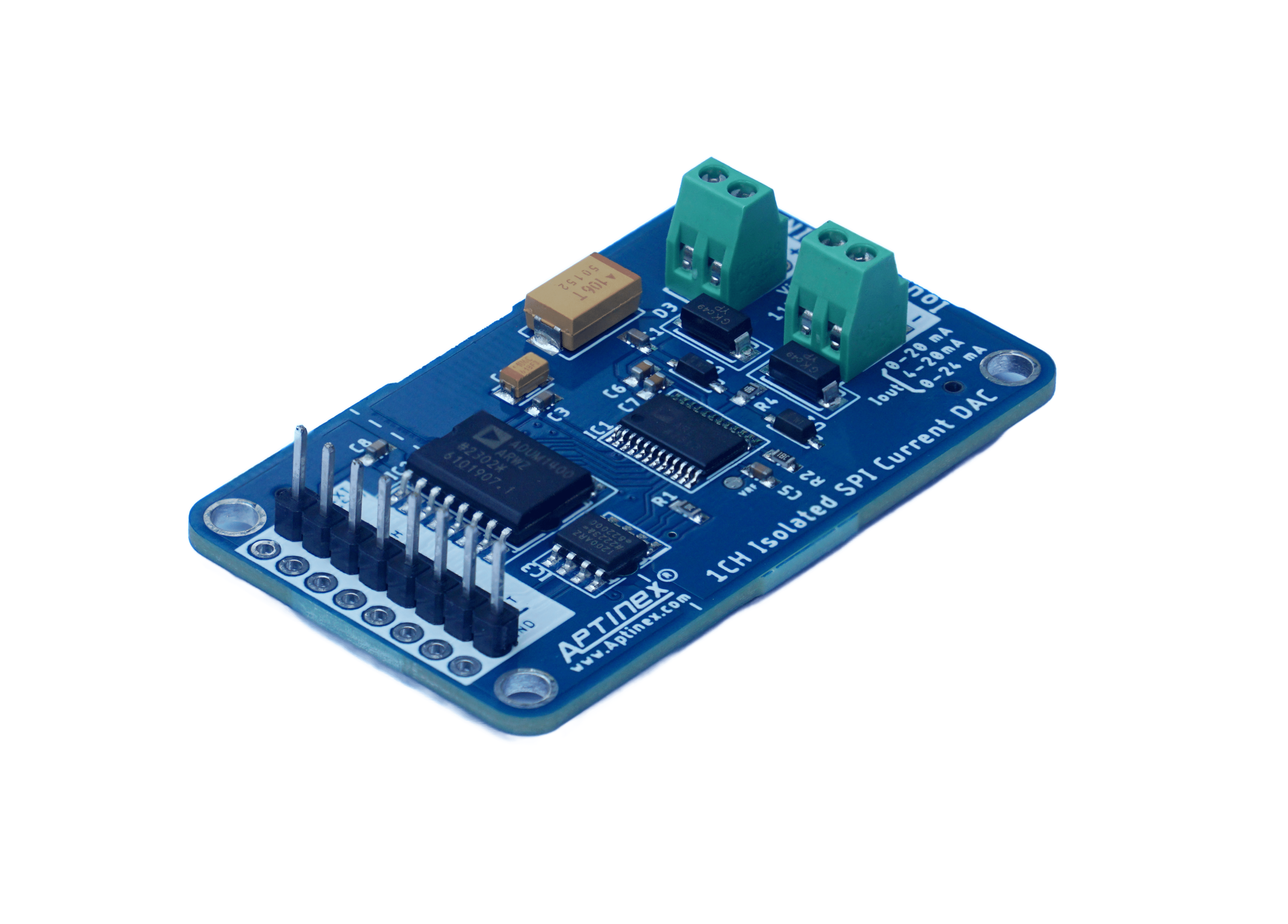
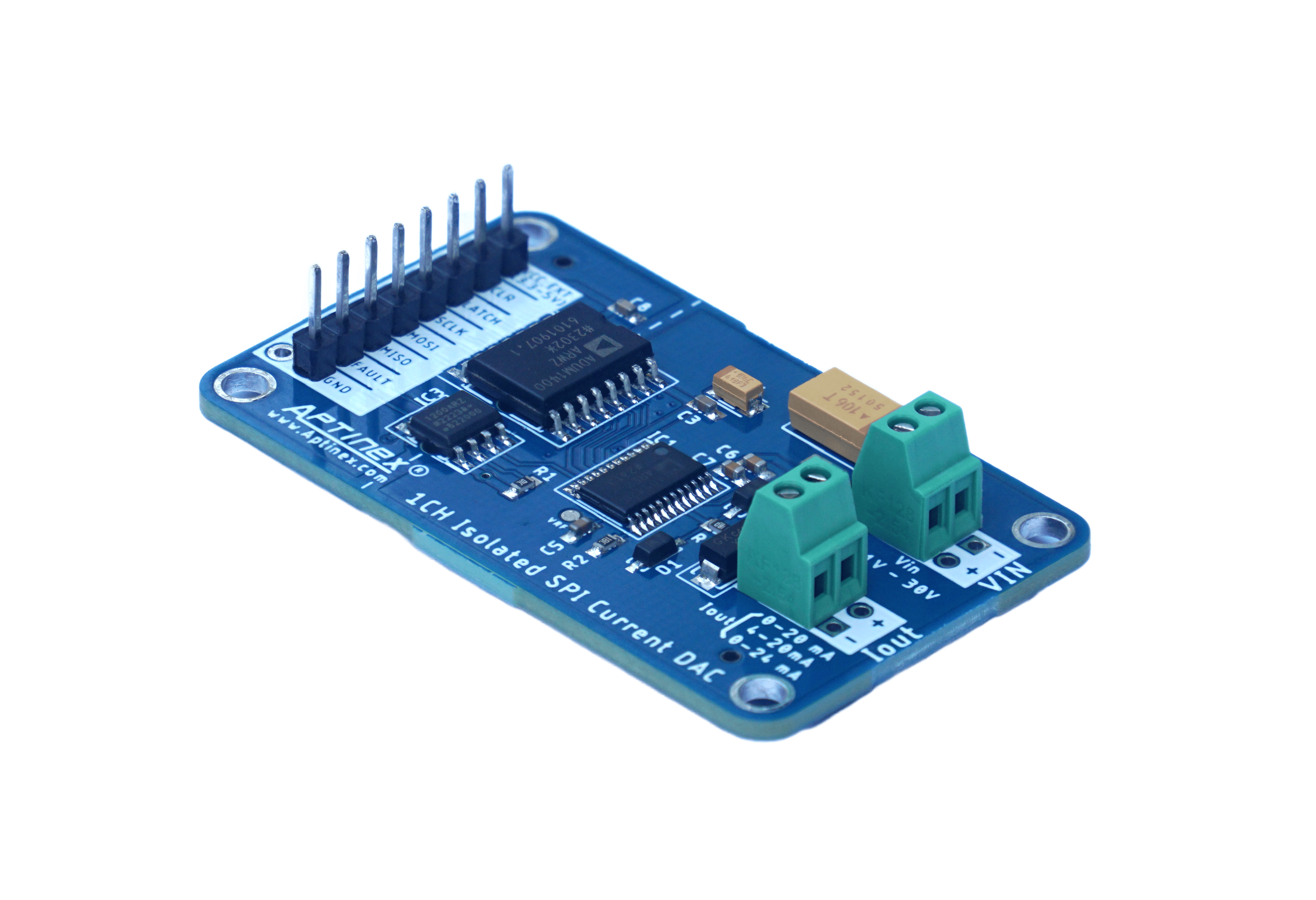
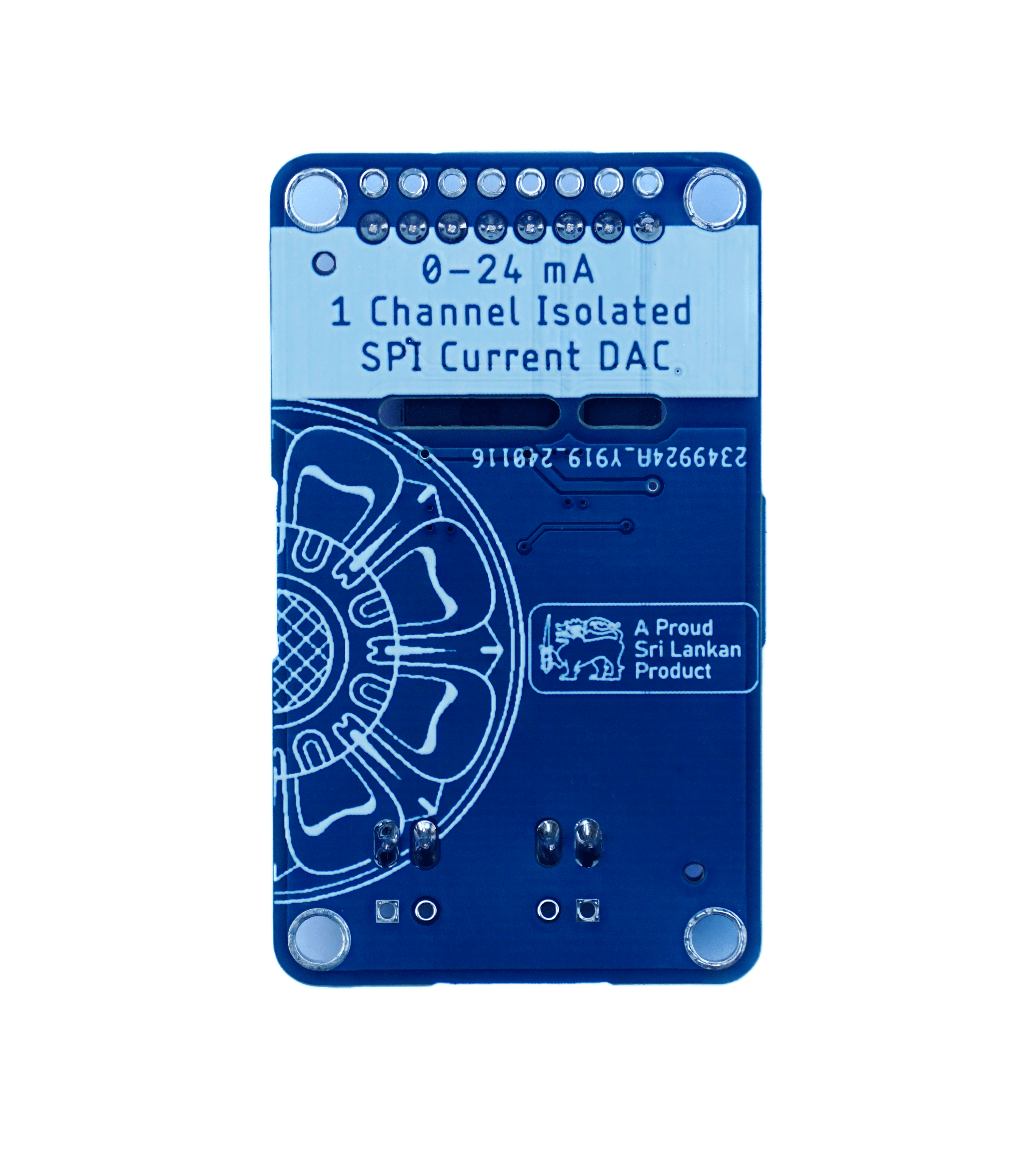
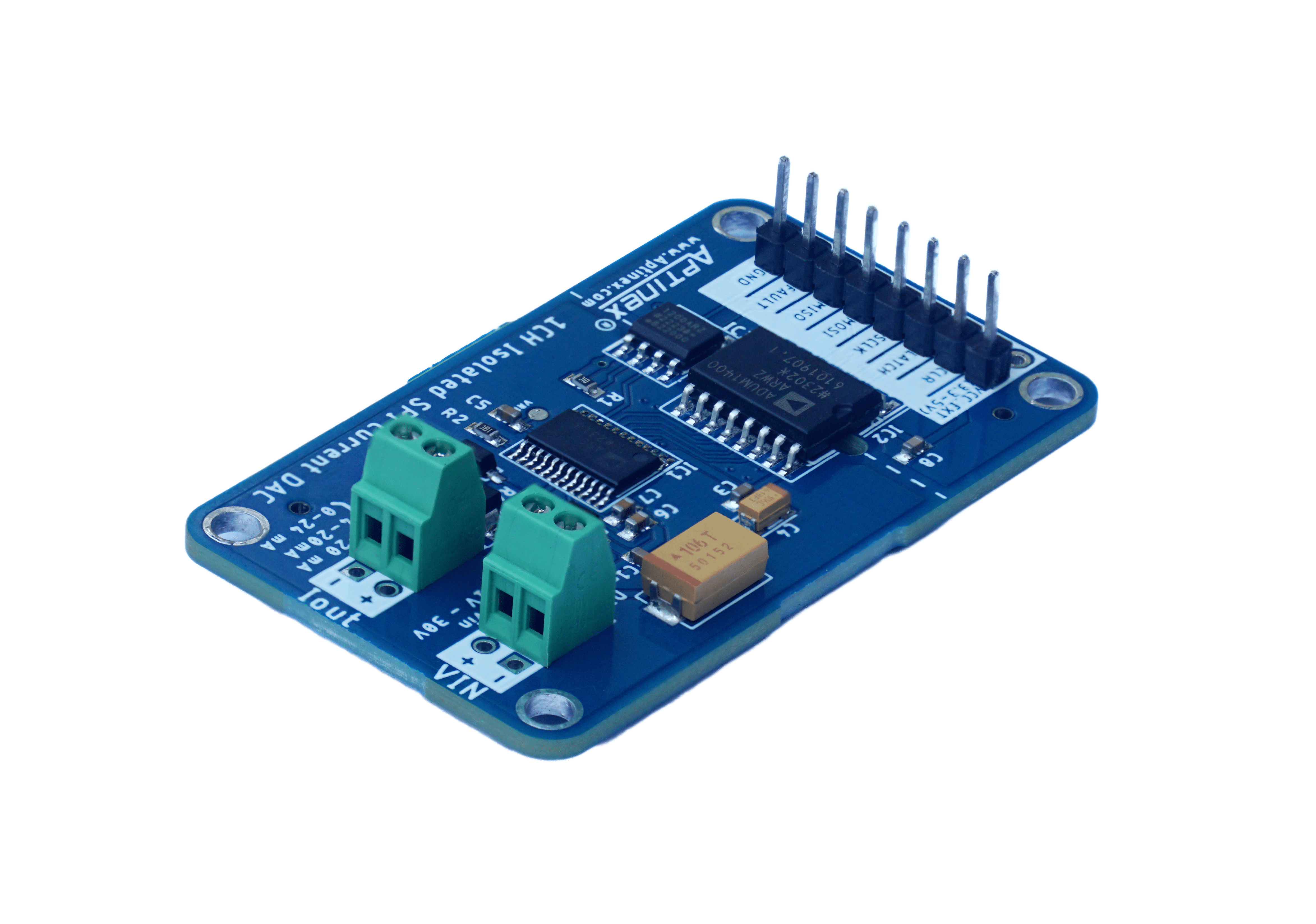
Introducing the Aptinex 1Channel SPI DAC Module DA1C024BS AD5420A, a masterpiece in digital-to-analog conversion designed for the highest demands of industrial precision and reliability. This module not only bridges digital control systems with analog operations but does so with unparalleled accuracy, ensuring that even the most minute digital instructions are translated into precise analog signals. Tailored for critical applications where precision is not just desired but required, the Aptinex DA1C024BS stands as a testament to engineering excellence, bringing digital control and analog execution into perfect harmony.
Features
- High-Resolution DAC: Employs the 16-bit AD5420A DAC, providing superior accuracy in signal conversion.
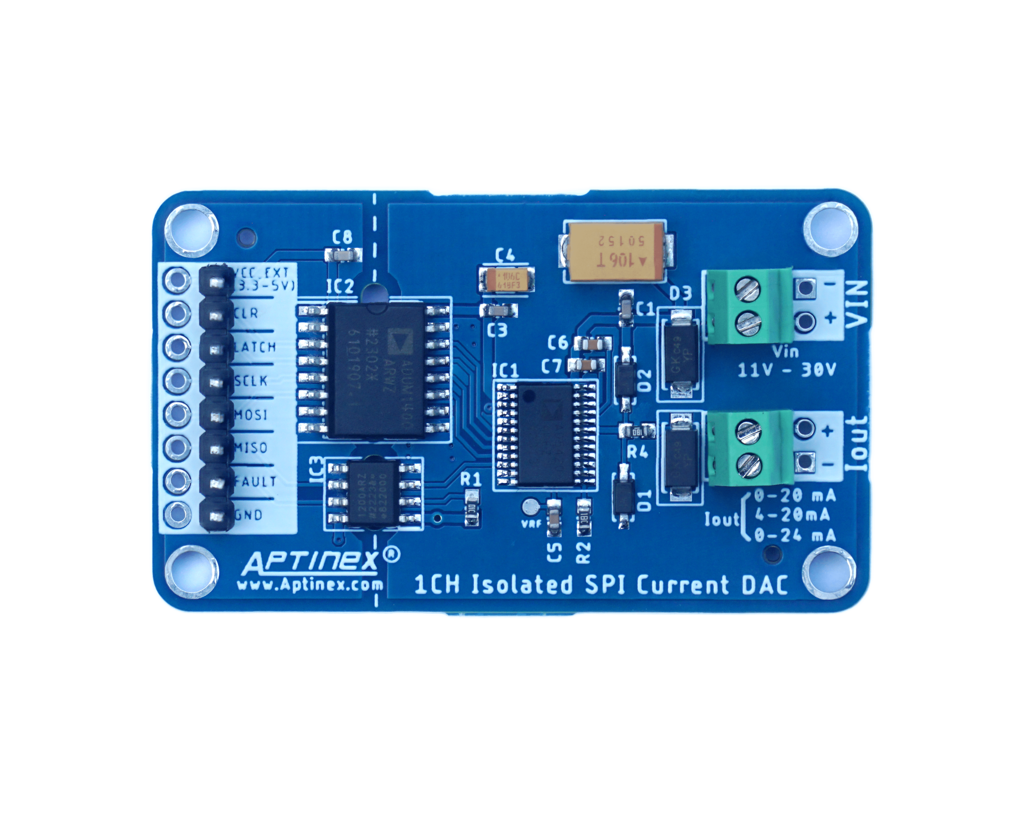
- Power Range: Operates across a broad voltage range of 11V to 30V, accommodating various industrial power setups.
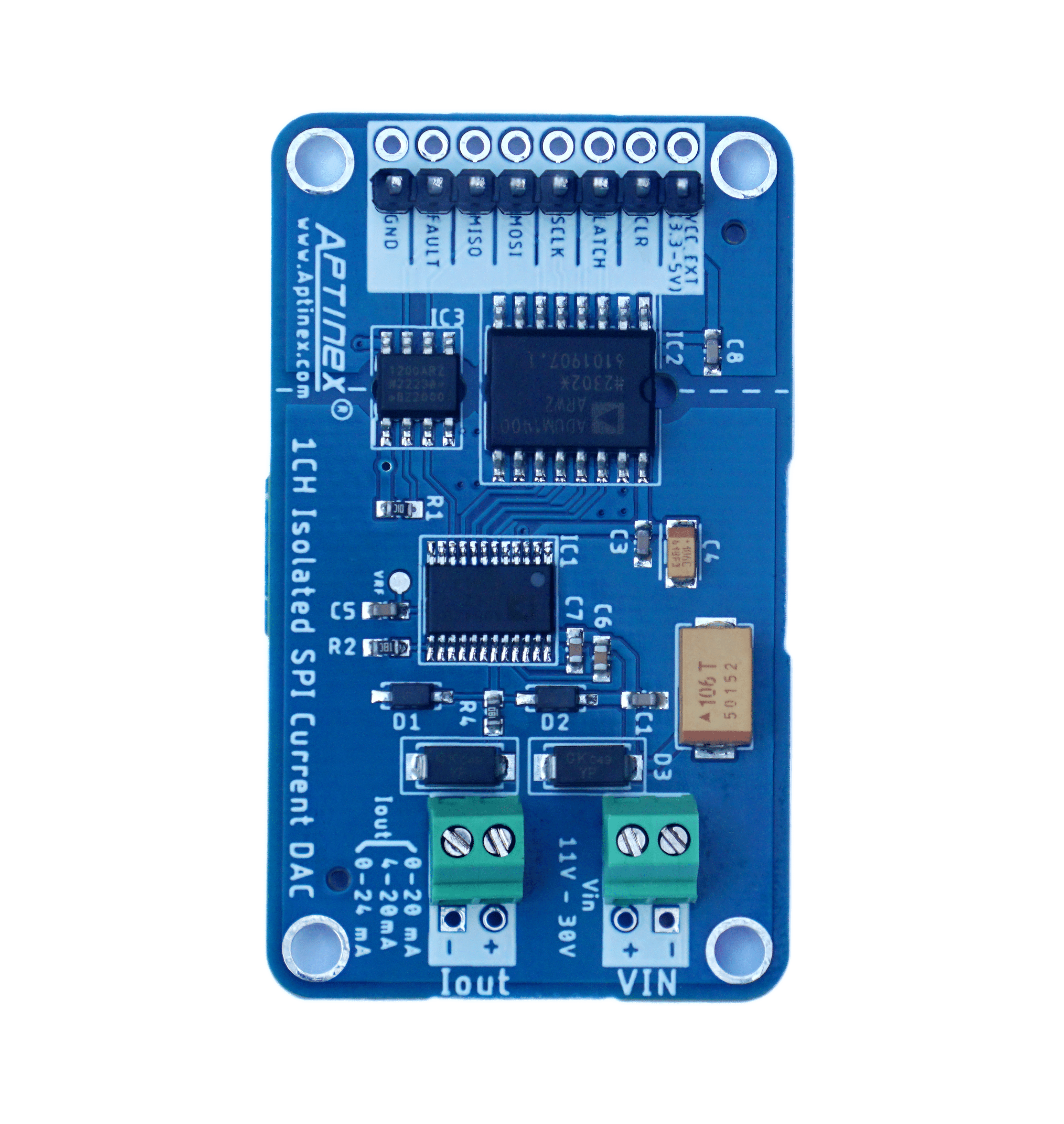
- Galvanic Isolation: Features comprehensive electrical isolation that prevents noise and interference, ensuring pristine signal integrity and enhancing safety.
Configurable Output Ranges: Supports flexible software-configurable outputs, including 0-24mA, 0-20mA, and 4-20mA, allowing for tailored application use.
SPI Communication: Facilitates robust and reliable digital communication, essential for integration into complex systems.
Industrial Durability: Designed to withstand harsh environmental conditions, ensuring durability and consistent performance.
At its heart lies the AD5420AREZ DAC, a component chosen for its high-resolution output. The module’s electrical integrity is fortified by the ADUM1400ARWZ and ADUM1200ARZ isolators, which act as vigilant guardians against transient spikes. The strategic placement of passive components supports optimal functioning, while protection circuits stand ready to defend against over-voltage incidents.
This DAC module is quintessential for processes where fidelity in signal conversion is paramount, such as in automated fluid dispensing, temperature control systems, and motor speed regulation. Its solid construction and protective features make it a valuable component in industries like petrochemical refining, pharmaceutical manufacturing, and precision machining.
Code Guide
To facilitate easy integration and demonstrate the functionality of the AmpWave – DA1C024BS DAC module, we provide a detailed code example tailored for use with Arduino platforms. This code snippet illustrates initial setup, dynamic control, and monitoring, enabling users to effectively manage the DAC’s capabilities and adapt its operation to suit specific application needs.
- Initialization and Setup:
// Begin serial communication and initialize DAC module

Serial.begin(115200);

dac_ad5420.begin();

dac_ad5420.ad5420_reset();

dac_ad5420.ad5420_write_ctrl(AD5420_OUTEN | AD5420_REXT | AD5420_0_24_RANGE);
This sets up the DAC module for operation, initializing it with the default current range and enabling outputs.
- Dynamic Output Control:
// Adjust DAC output based on serial input for real-time testing and calibration

if (Serial.available() > 0) {

char ch = Serial.read();

int value = (ch - '0') * 0x1000; // Convert input to hexadecimal value

dac_ad5420.ad5420_write_data(value);

}
Users can dynamically control the DAC’s output via serial commands, which is ideal for adjusting settings during operational testing.
- Output Range Configuration:
// Configure output range based on user input to adapt to different operational needs

switch(userInput) {

case 'A':

dac_ad5420.ad5420_write_ctrl(AD5420_0_24_RANGE); // 0-24mA

break;

case 'B':

dac_ad5420.ad5420_write_ctrl(AD5420_0_20_RANGE); // 0-20mA

break;

case 'C':

dac_ad5420.ad5420_write_ctrl(AD5420_4_20_RANGE); // 4-20mA

break;

}
This shows how to switch between different current output ranges, allowing the module to be used in various application scenarios.
- Continuous System Monitoring:
// Continuously check and display the DAC status for troubleshooting and system checks

Serial.print("Current DAC Status: ");

Serial.println(dac_ad5420.ad5420_get_status(), HEX);
Regular monitoring of the DAC’s status is vital for ensuring operational integrity and reliability.
The AmpWave – DA1C024BS from Aptinex is a pinnacle of digital-to-analog conversion technology, expertly blending high precision with robust reliability. Equipped with a 16-bit DAC, galvanic isolation, and flexible SPI communication, this module excels in various demanding environments, from industrial automation to scientific research. Its comprehensive features and straightforward implementation make it an essential tool for professionals seeking optimal control and efficiency in their projects.
Sample Code
| #include <ad5420.h> | |
| /* | |
| Use the 6 pin SPI connector on arduino DUE board (NOT the ICSP!) | |
| The pin 1 has a white dot behind it. | |
| MOSI: | |
| MISO: | |
| SCLK: | |
| CS: on SPI extended mode can use only PIN 4,10,52 !!! | |
| */ | |
| #define AD5420_FAULT 8 | |
| #define AD5420_CLEAR 9 | |
| #define AD5420_LATCH 10 //CS | |
| //MOSI —-> Arduino MOSI pin | |
| //MISO—-> Arduino MISO pin | |
| //SCLK—-->—-> Arduino SPI CLK pin | |
| DAC_AD5420 dac_ad5420 = DAC_AD5420(AD5420_LATCH, AD5420_CLEAR, AD5420_FAULT); | |
| uint16_t current = 0; | |
| void setup() { | |
| Serial.begin(115200); //Serial Com Begin | |
| Serial.println(“AD5420_01_test start!”); | |
| Serial.print(“_latch = “); | |
| Serial.println(dac_ad5420._latch); | |
| Serial.print(“_clear = “); | |
| Serial.println(dac_ad5420._clear); | |
| Serial.print(“_fault = “); | |
| Serial.println(dac_ad5420._fault); | |
| dac_ad5420.begin(); //SPI Communication Begin with AD5420 | |
| delay(100); | |
| dac_ad5420.ad5420_reset(); //AD5420 Registers rest | |
| delay(100); | |
| //AD5420 Intialize (O/P Enable and Range Select) | |
| //AD5420_0_24_RANGE —--> 0-24mA | |
| //AD5420_4_20_RANGE —-->4-20mA | |
| //AD5420_0_20_RANGE —-->0-20mA | |
| dac_ad5420.ad5420_write_ctrl(AD5420_OUTEN | AD5420_REXT | AD5420_0_24_RANGE); | |
| // dac_ad5420.ad5420_write_data(0x2000); | |
| dac_ad5420.ad5420_write_data(current); //Write 0X0000 —->O/P Current 0mA , 4mA | |
| } | |
| void loop() { | |
| Serial.print(“Get_Status: “); | |
| Serial.println(dac_ad5420.ad5420_get_status(), HEX); | |
| Serial.print(“Status_Reg: “); | |
| Serial.println(dac_ad5420.ad5420_read_reg(AD5420_STATUS_REG), HEX); | |
| Serial.print(“Data_Reg: “); | |
| Serial.println(dac_ad5420.ad5420_read_reg(AD5420_DATA_REG), HEX); | |
| Serial.print(“Control_Reg: “); | |
| Serial.println(dac_ad5420.ad5420_read_reg(AD5420_CONTROL_REG), HEX); | |
| if (Serial.available() > 0) { | |
| char ch = Serial.read(); // Clean the input buffer | |
| if (ch == ‘0’) dac_ad5420.ad5420_write_data(0x0000); | |
| else if (ch == ‘1’) dac_ad5420.ad5420_write_data(0x1000); | |
| else if (ch == ‘2’) dac_ad5420.ad5420_write_data(0x2000); | |
| else if (ch == ‘3’) dac_ad5420.ad5420_write_data(0x3000); | |
| else if (ch == ‘4’) dac_ad5420.ad5420_write_data(0x4000); | |
| else if (ch == ‘5’) dac_ad5420.ad5420_write_data(0x5000); | |
| else if (ch == ‘6’) dac_ad5420.ad5420_write_data(0x6000); | |
| else if (ch == ‘7’) dac_ad5420.ad5420_write_data(0x7000); | |
| else if (ch == ‘8’) dac_ad5420.ad5420_write_data(0x8000); | |
| else if (ch == ‘9’) dac_ad5420.ad5420_write_data(0x9000); | |
| else if (ch == ‘A’) dac_ad5420.ad5420_write_data(0xA000); | |
| else if (ch == ‘B’) dac_ad5420.ad5420_write_data(0xB000); | |
| else if (ch == ‘C’) dac_ad5420.ad5420_write_data(0xC000); | |
| else if (ch == ‘D’) dac_ad5420.ad5420_write_data(0xD000); | |
| else if (ch == ‘E’) dac_ad5420.ad5420_write_data(0xE000); | |
| else if (ch == ‘F’) dac_ad5420.ad5420_write_data(0xF000); | |
| else if (ch == ‘G’) dac_ad5420.ad5420_write_data(0xFFFF); | |
| } | |
| delay(200); | |
| } |
Related products
Motor Controllers
Data Conversion
Power Control

