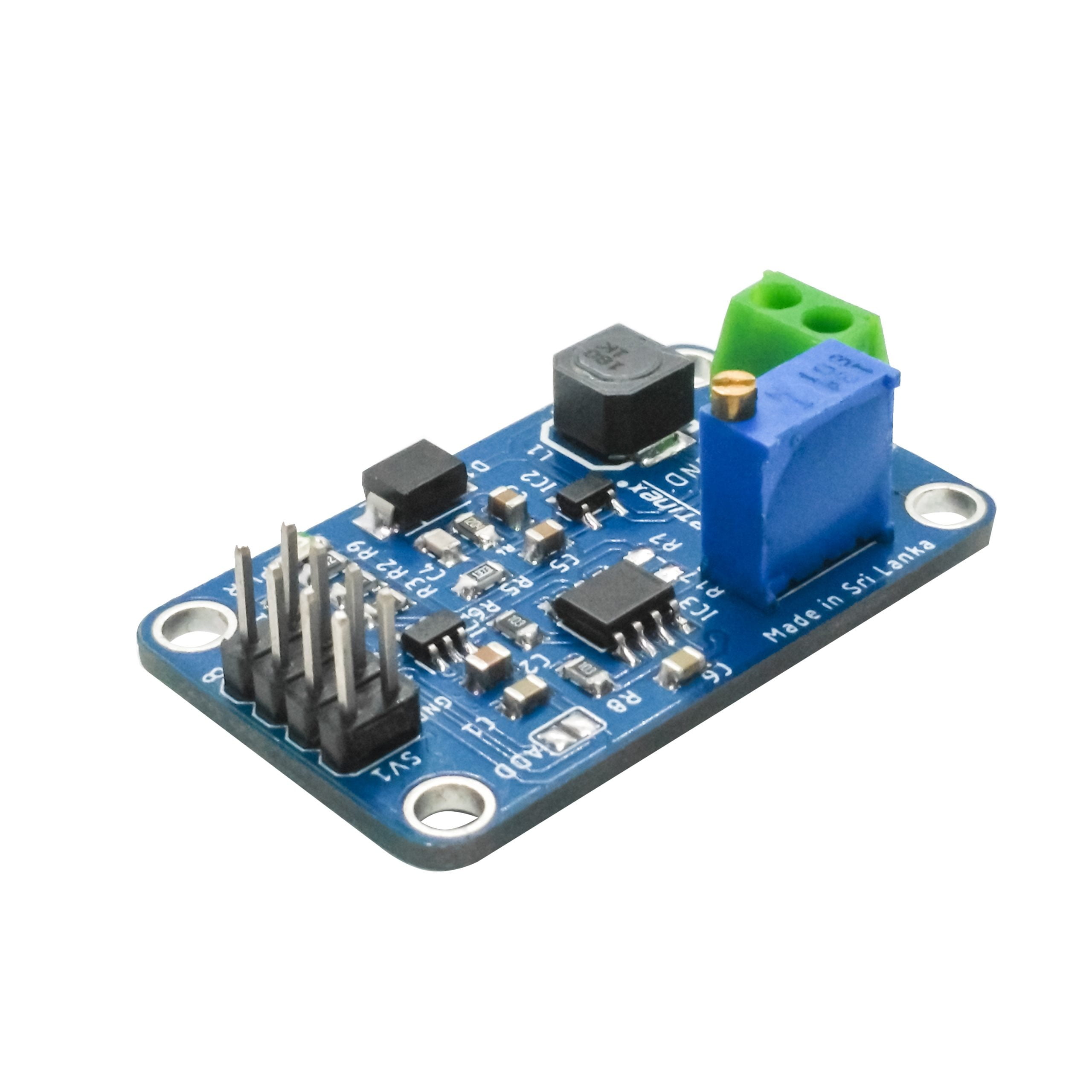
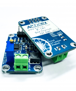
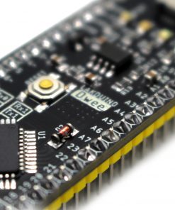
Aptinex DAC Module DA1C010BI I2C Digital to Analog 0-10V MCP4725
$29.90
5 in stock (can be backordered)
Key Features
- No of Channels : 1
- PCB Dimension : 2.5cm x 4.0cm
- PCB Color: Blue
- I2C Connectivity: Seamless integration with microcontrollers and digital devices via male headers.
-
Stable Power Supply: Operates reliably on a 5V DC power source.
-
Visual Confirmation: Power LED indicator for immediate operational status feedback.
-
Secure Installation: Four strategically positioned mounting holes for stable and adaptable installations.
-
Effortless Output: Output facilitated through a dependable screw terminal.
-
Precision DAC: Utilizes the MCP4725A, a 12-bit digital-to-analog converter, for unparalleled accuracy in analog voltage outputs.
-
Integrated Non-Volatile Memory (EEPROM): Allows for the preservation of DAC register and configuration bit values at power off.
-
Flexible I2C Address Configuration: Part number code-based I2C address selection within the SOT-23 package.
-
High Resolution: 12-bit resolution for fine-grained control of analog voltages.
-
Wide Output Range: Rail-to-rail output for maximum dynamic range.
-
Efficient Power Consumption: Low power consumption which is ideal for battery-powered applications.
-
Extended Temperature Range: Operational in environments ranging from -40°C to +125°C.
-
Automotive-Grade Reliability: AEC-Q100 Grade 1 qualified, suitable for stringent automotive applications.
-
Multiple Speed Modes: Supports Standard (100 kbps), Fast (400 kbps), and High Speed (3.4 Mbps) I2C modes.
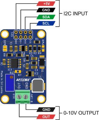
Locating the I2C Address for MCP4725A 12 Bit DAC IC
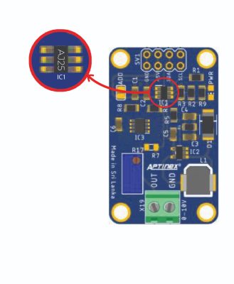
The I2C address configuration for the MCP4725A IC enclosed in the SOT-23 package is directly linked to its part number. Specifically, the initial two letters of the part number bear crucial information, whereas the subsequent characters (represented by XX) can encompass any combination of numbers or letters. This correlation is outlined as follows:
Deciphering the part number code, pivotal in ascertaining the I2C address configuration, can be achieved through a thorough examination of the DAC IC. For a visual aid, please refer to the image below.
Using a Single DAC Module:
In this setup, XX can represent any combination of numbers or letters. It is crucial to focus on the initial two letters for identification purposes.
| Part Number Code | Part No | Address |
| AJXX | MCP4725A0T-E/CH | 0x60 |
| APXX | MCP4725A1T-E/CH | 0x62 |
| AQXX | MCP4725A2T-E/CH | 0x64 |
| ARXX | MCP4725A3T-E/CH | 0x66 |
Connecting 2 DAC Modules to the I2C Bus:
When employing 2 DAC modules on the I2C bus, ensure that only one DAC module has the “Add” named soldering jumper applied. For visual guidance, please refer to the image below.

In this setup, XX can represent any combination of numbers or letters. It is crucial to focus on the initial two letters for identification purposes.
| Part Number Code | Part No | Address 1 | Address 2 |
| AJXX | MCP4725A0T-E/CH | 0x60 | 0x61 |
| APXX | MCP4725A1T-E/CH | 0x62 | 0x63 |
| AQXX | MCP4725A2T-E/CH | 0x64 | 0x65 |
| ARXX | MCP4725A3T-E/CH | 0x66 | 0x67 |
Three modes of operation are supported.
- standard 100kbps
- fast 400kbps
- high speed 3.4Mbps
It is possible to interface this DAC module with the following platforms.
- Raspberry Pi
- Arduino
- Onion Omega
- Beaglebone
- Windows,
- Particle Photon
Applications
- Sensor Interfacing
- Audio Processing
- Instrumentation and Control Systems
- Calibration and Testing
- Signal Generation
Sample Codes
Download Sample | Download Library
| #include <Wire.h> | |
| #include “Aptinex_MCP4725.h“ | |
| Aptinex_MCP4725 dac; | |
| void setup(void) { | |
| Serial.begin(115200); | |
| Serial.println(“***APTINEX MCP4725A DAC MODULE TEST CODE***“); | |
| // For Aptinex MCP4725A1 the address is 0x62 (default) or 0x63 (ADDR pin tied to VCC) | |
| // For MCP4725A0 the address is 0x60 or 0x61 | |
| // For MCP4725A2 the address is 0x64 or 0x65 | |
| dac.begin(0x62); | |
| Serial.println(“First, Enter H and adjust pot for the maximum value (10v) “); // measure DAC output voltage with multimeter | |
| Serial.println(“Enter H for maximum value“); // DAC output will be set to the maximum value | |
| Serial.println(“Enter M for medium value“); // DAC output will be set to the medium value | |
| Serial.println(“Enter L for lowest value“); // DAC output will be set to the lowest value | |
| } | |
| void loop(void) { | |
| uint32_t counter; | |
| char incomingByte; | |
| if (Serial.available() > 0) { | |
| // read the oldest byte in the serial buffer: | |
| incomingByte = Serial.read(); | |
| if (incomingByte == ‘H‘) { | |
| counter = 0xFFF; | |
| dac.setVoltage(counter, false); | |
| Serial.println(counter); | |
| delay(100); | |
| } | |
| else if (incomingByte == ‘M‘) { | |
| counter = 0x800; | |
| dac.setVoltage(counter, false); | |
| Serial.println(counter); | |
| delay(100); | |
| } | |
| else if (incomingByte == ‘L‘) { | |
| counter = 0x000; | |
| dac.setVoltage(counter, false); | |
| Serial.println(counter); | |
| delay(100); | |
| } | |
| } | |
| } |
|
import smbus
|
|
|
import time
|
|
|
# Define the I2C address of the MCP4725 DAC
|
|
|
DAC_ADDRESS = 0x60
|
|
|
# Define the register addresses for the MCP4725
|
|
|
DAC_REG_WRITE = 0x40
|
|
|
DAC_REG_WRITE_EEPROM = 0x60
|
|
|
# Initialize the I2C bus (you may need to change the bus number)
|
|
|
bus = smbus.SMBus(1)import smbus
|
|
|
import time
|
|
|
# Define the I2C address of the MCP4725 DAC
|
|
|
DAC_ADDRESS = 0x60
|
|
|
# Define the register addresses for the MCP4725
|
|
|
DAC_REG_WRITE = 0x40
|
|
|
DAC_REG_WRITE_EEPROM = 0x60
|
|
|
# Initialize the I2C bus (you may need to change the bus number)
|
|
|
bus = smbus.SMBus(1)
|
|
|
# Function to set the DAC output voltage
|
|
|
def set_dac_voltage(voltage):
|
|
|
# Calculate the 12-bit value from the desired voltage (0-4095)
|
|
|
value = int((voltage / 10) * 4095)
|
|
|
# Split the value into two bytes
|
|
|
data = [(value >> 4) & 0xFF, (value << 4) & 0xFF]
|
|
|
# Write the value to the DAC register
|
|
|
bus.write_i2c_block_data(DAC_ADDRESS, DAC_REG_WRITE, data)
|
|
|
# Function to set DAC O/P voltage and save value to the MCP4725 EEPROM
|
|
|
def set_dac_voltage_EEPROM(voltage):
|
|
|
# Calculate the 12-bit value from the desired voltage (0-4095)
|
|
|
value = int((voltage / 10) * 4095)
|
|
|
# Split the value into two bytes
|
|
|
data = [(value >> 4) & 0xFF, (value << 4) & 0xFF]
|
|
|
# Write the value to the DAC register
|
|
|
#bus.write_i2c_block_data(DAC_ADDRESS, DAC_REG_WRITE, data)
|
|
|
# Optionally, save the value to EEPROM for persistence after power-off
|
|
|
bus.write_i2c_block_data(DAC_ADDRESS, DAC_REG_WRITE_EEPROM, data)
|
|
|
# Clean up and release the I2C bus
|
|
|
#bus.close()
|
|
|
#SETUP
|
|
|
print(“***APTINEX MCP4725A DAC MODULE TEST CODE***”)
|
|
|
print(“First, Enter H and adjust pot for the maximum value (10v) “) #This is im>
|
|
|
print(“Enter H for maximum value 10.0V”)
|
|
|
print(“Enter M for medium value 5.0V”)
|
|
|
print(“Enter L for lowest value 0V”)
|
|
|
print(“\n”)
|
|
|
while True:
|
|
|
user_input = input()
|
|
|
if user_input == ‘H’:
|
|
|
set_dac_voltage(10)
|
|
|
print(“DAC O/P set to 10.0V”)
|
|
|
time.sleep(0.1)
|
|
|
elif user_input == ‘M’:
|
|
|
set_dac_voltage(5)
|
|
|
print(“DAC O/P set to 5.0V”)
|
|
|
time.sleep(0.1)
|
|
|
elif user_input == ‘L’:
|
|
|
set_dac_voltage(0)
|
|
|
print(“DAC O/P set to 0V”)
|
|
|
time.sleep(0.1)
|
|
|
else:
|
|
|
print(“Invalid input. Please enter H, M, or L.”)
|
| #include <Wire.h> | |
| void setup() | |
| { | |
| Wire.begin(); | |
| Serial.begin(9600); | |
| while (!Serial); // Leonardo: wait for serial monitor | |
| Serial.println(“nI2C Scanner”); | |
| } | |
| void loop() | |
| { | |
| byte error, address; | |
| int nDevices; | |
| Serial.println(“Scanning…”); | |
| nDevices = 0; | |
| for(address = 1; address < 127; address++ ) | |
| { | |
| // The i2c_scanner uses the return value of the Write.endTransmisstion to see if a device did acknowledge to the address. | |
| Wire.beginTransmission(address); | |
| error = Wire.endTransmission(); | |
| if (error == 0) | |
| { | |
| Serial.print(“I2C device found at address 0x”); | |
| if (address<16) | |
| Serial.print(“0”); | |
| Serial.print(address,HEX); | |
| Serial.println(” !”); | |
| nDevices++; | |
| } | |
| else if (error==4) | |
| { | |
| Serial.print(“Unknown error at address 0x”); | |
| if (address<16) | |
| Serial.print(“0”); | |
| Serial.println(address,HEX); | |
| } | |
| } | |
| if (nDevices == 0) | |
| Serial.println(“No I2C devices found\n”); | |
| else | |
| Serial.println(“done\n”); | |
| delay(5000); // wait 5 seconds for next scan | |
| } |
| Weight | 50 g |
|---|
Related products
Line Hunting Sensors
Raykha S8 – TCRT5000 based 8 channel Reflective Sensor Array
LuminaDALI
Lakduino

